
Hybrid random fiber laser distributed amplification method based on erbium fiber with low doping concentration

a distributed amplification and random fiber technology, applied in the field of erbium fiber with low doping concentration, can solve the problem of signal-to-noise ratio (snr) at the far end of the fiber, and achieve the effects of low convention efficiency, reduced snr degradation rate, and high threshold

Active Publication Date: 2019-02-21
UNIV OF ELECTRONICS SCI & TECH OF CHINA
View PDF19 Cites 3 Cited by
  • Summary
  • Abstract
  • Description
  • Claims
  • Application Information

AI Technical Summary

Benefits of technology

The present invention provides a hybrid distributed amplification method using random lasing generated within WEDF. This method solves the problem of high laser threshold and low conversion efficiency when using conventional optical fiber. By combining a pump source, a wavelength division multiplexer, and a strong feedback module to generate a random fiber laser, this random fiber laser is used as the amplifying pump for WEDF while performing distributed Raman amplification at the same time. This joint construction reduces the degradation rate of SNR along the fiber, allowing for long-distance fiber communication and sensing systems. Additionally, the invention slows down pump consumption, reduces spontaneous emission noise, and generates a higher SNR, resulting in a more equalized gain distribution and reduced degradation of SNR. Overall, this invention provides a more efficient and equalized amplification solution for fiber transmission or sensing systems.

Problems solved by technology

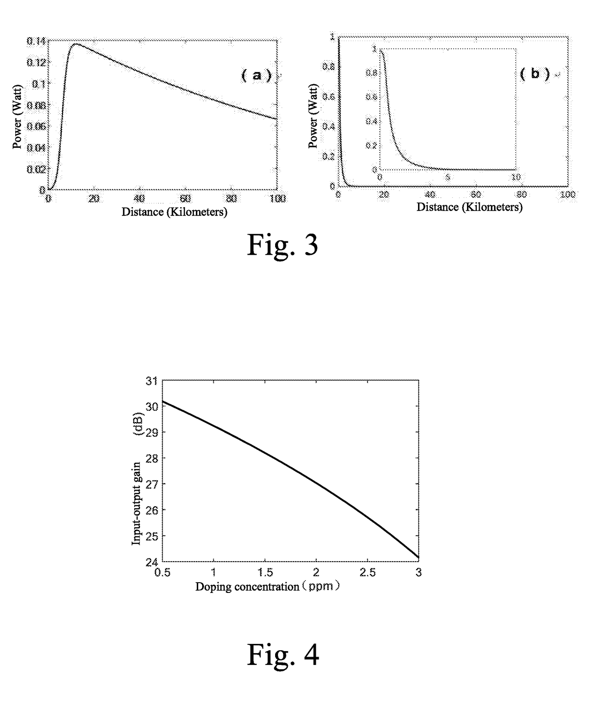
On the other hand, it also solves the problem, i.e. when the EDF with high doping concentration is used, the pump energy consumes rapidly, resulting in the degradation in signal-to-noise ratio (SNR) at the far end of the fiber.

Method used


Image

  • Hybrid random fiber laser distributed amplification method based on erbium fiber with low doping concentration
  • Hybrid random fiber laser distributed amplification method based on erbium fiber with low doping concentration
  • Hybrid random fiber laser distributed amplification method based on erbium fiber with low doping concentration

Examples


embodiment 1

[0055]A hybrid distributed amplification method based on random lasing generated within WEDF, comprises steps of:

[0056]step (1) constructing a fiber link via WEDF;

[0057]step (2) combined with the pump source, the wavelength division multiplexer and the strong feedback module, generating a random fiber laser based on the fiber link;

[0058]step (3) constructing a pump for amplification of WEDF based on the random fiber laser, meanwhile performing distributed Raman amplification by the random fiber laser, so that a distributed amplification method using the hybrid of WEDF and Raman effects is capable of constructing a spatially equalized gain distribution along the fiber; and

[0059]step (4) performing hybrid distributed amplification within WEDF and the Raman fiber random laser to achieve spatially equalized gain distribution along the fiber.

[0060]As shown in FIG. 6, a concentration of the EDF is taken at any value in a range from 0.1 ppm to 3 ppm. The reason of choosing WEDF is that, th...

embodiment 2

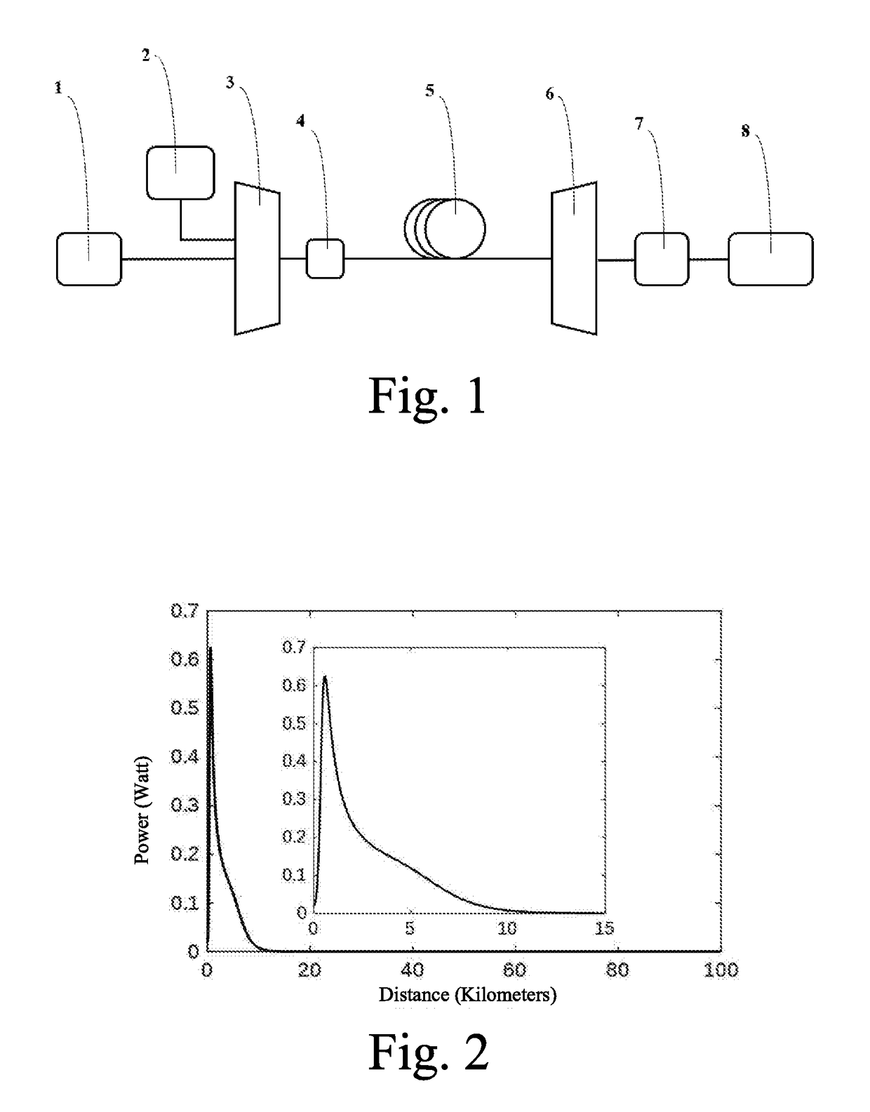
[0061]A long-distance optical fiber transmission system, comprising a signal transmitter 1, a wavelength division multiplexer A 3, a wavelength division multiplexer B 6, a signal receiver 8, a pump source 2, a WEDF 5, a strong feedback module 4, and a filter 7, as shown in FIG. 1;

[0062]In the optical fiber transmission system within 1550 nm waveband, the doping concentration of the EDF 5 is set as 1.5 ppm. The signal transmitter 1 emits continuous light with 1550 nm wavelength and 0.0001 W output power, and pumping source 2 is a high-power fiber laser with 1365 nm wavelength and 1.5 W output power. Both the wavelength division multiplexer A 3 and the wavelength division multiplexer B 6 have two multiplexing ports of 1550 nm and 1365 nm. The strong feedback module 4 is the fiber Bragg grating with a center wavelength of 1480 nm. The length of the WEDF 5 is 100 km. The signal transmitter 1 generates a signal, and the signal transmits into the WEDF 5 through the wavelength division mul...

embodiment 3

[0068]A fiber distributed acoustic sensing system, comprising a signal generating module 9, a circulator 10, a signal receiving and demodulation module 12, a wavelength division multiplexer 11, a pump source 2, a strong feedback module 4, a WEDF 5 and a filter 7. The signal generating module 9 is connected to the first port of the circulator 10, the wavelength division multiplexer 11 is connected to the second port of the circulator 10, the third port of the circulator 10 is connected to the signal receiving and demodulation module 12. Preferably, the input of the filter 7 is connected to the third port of the circulator 10, and the output of the filter 7 is connected to the signal receiving and demodulation module 12. The above expressions are shown in FIG. 5. In the optical fiber sensing system within 1550 nm waveband, the doping concentration of the WEDF 5 is 1.5 ppm. The signal generating module 9 generates a modulated sensing signal, which is input into the wavelength division ...


PUM


Abstract

A hybrid distributed amplification method based on a random fiber laser generated within erbium fiber with low doping concentration, i.e. weak erbium-doped fiber (WEDF), which includes: Step 1. constructing a fiber link via WEDF; Step 2. generating the random fiber laser based on the fiber link, the pump source, the wavelength division multiplexer and the strong feedback module; Step 3. constructing the spatial equalized gain based on hybrid gain of the erbium fiber and random fiber laser; Step 4. the signal is amplified by the hybrid spatial equalized gain. The present invention solves the typical problem of high laser threshold and low pump conversion efficiency when conventional fiber is used to generate random fiber laser for distributed amplification.

Description

CROSS REFERENCE OF RELATED APPLICATION[0001]The present application claims priority under 35 U.S.C. 119(a-d) to CN 201810759850.8, filed Jul. 11, 2018.BACKGROUND OF THE PRESENT INVENTIONField of Invention[0002]The present invention relates to the field of amplification methods for long-distance optical fiber communication and long-distance optical fiber sensing, and more particularly to a hybrid distributed amplification method based on random lasing generated within erbium-doped fiber (EDF) with low doping concentration, i.e. weak erbium-doped fiber (WEDF).Description of Related Arts[0003]Optical fiber communication and sensing technologies have been widely used in various fields of modern society. The transmission or sensing distance of optical fiber communication or sensing systems is an important indicator of system performance. Adding a repeater with an erbium-doped fiber amplifier (EDFA) in the middle of the fiber link is an important means to extend the transmission or sensin...

Claims


Application Information

Patent Timeline
Patent Type & Authority Applications(United States)
IPC IPC(8): H04B10/25H04J14/02H04B10/50
CPCH04B10/25H04J14/02H04B10/503H01S3/06716H01S3/06754H01S3/094046H04B10/2912H04B10/2916
Inventor RAO, YUNJIANGFU, YUNLI, JIAQIWANG, ZINAN
Owner UNIV OF ELECTRONICS SCI & TECH OF CHINA
Learn More