Precision Operator for an Aircraft Autothrottle or Autopilot System with Engine Performance Adjust

a technology of autopilot system and precision operator, which is applied in the direction of engine starter, engine/propulsion engine ignition, instruments, etc., can solve the problem of relatively light invention arrangement, and achieve the effect of increasing or decreasing the tension required to adjust the throttle lever

Active Publication Date: 2019-02-14
INNOVATIVE SOLUTIONS & SUPPORT
View PDF3 Cites 16 Cited by
  • Summary
  • Abstract
  • Description
  • Claims
  • Application Information

AI Technical Summary

Benefits of technology

[0023]According to one aspect of the invention, a tension required to adjust the throttle lever(s) is increased or decreased based at least in part on the nonconforming condition.
[0024]According to one aspect of the invention the auto-throttle acts at and on power lever cables going to the engine. The autothrottle can also provide FADEC type engine protection. The actuator can be mounted on the engine at the cable attachment point. This adaptation has heretofore not been adapted because of the bulk of conventional auto-throttles and the high temperatures around the engine, especially after shutdown. The present implementation uses a stepper motor and therefore lends itself to remotely mounting the electronic control in a more moderate, nearby environment. The disclosed linear actuator has an instinctively safe clutch assuring manual override. The actuator shuttle would act directly on or near the power cable attachment to the fuel control valve. It will back drive the power lever in the cockpit. The stepper motor is mounted with the motor drive circuitry in the existing interface protection box. Additionally, an accordion protection sleeve is provided on the rotating drive shaft to protect it from oil and fluids contamination.

Problems solved by technology

First, the inventive arrangement is relatively lightweight, especially as compared to current autopilot / autothrottle operating arrangements and components.

Method used


Image

  • Precision Operator for an Aircraft Autothrottle or Autopilot System with Engine Performance Adjust
  • Precision Operator for an Aircraft Autothrottle or Autopilot System with Engine Performance Adjust
  • Precision Operator for an Aircraft Autothrottle or Autopilot System with Engine Performance Adjust

Examples


Embodiment Construction

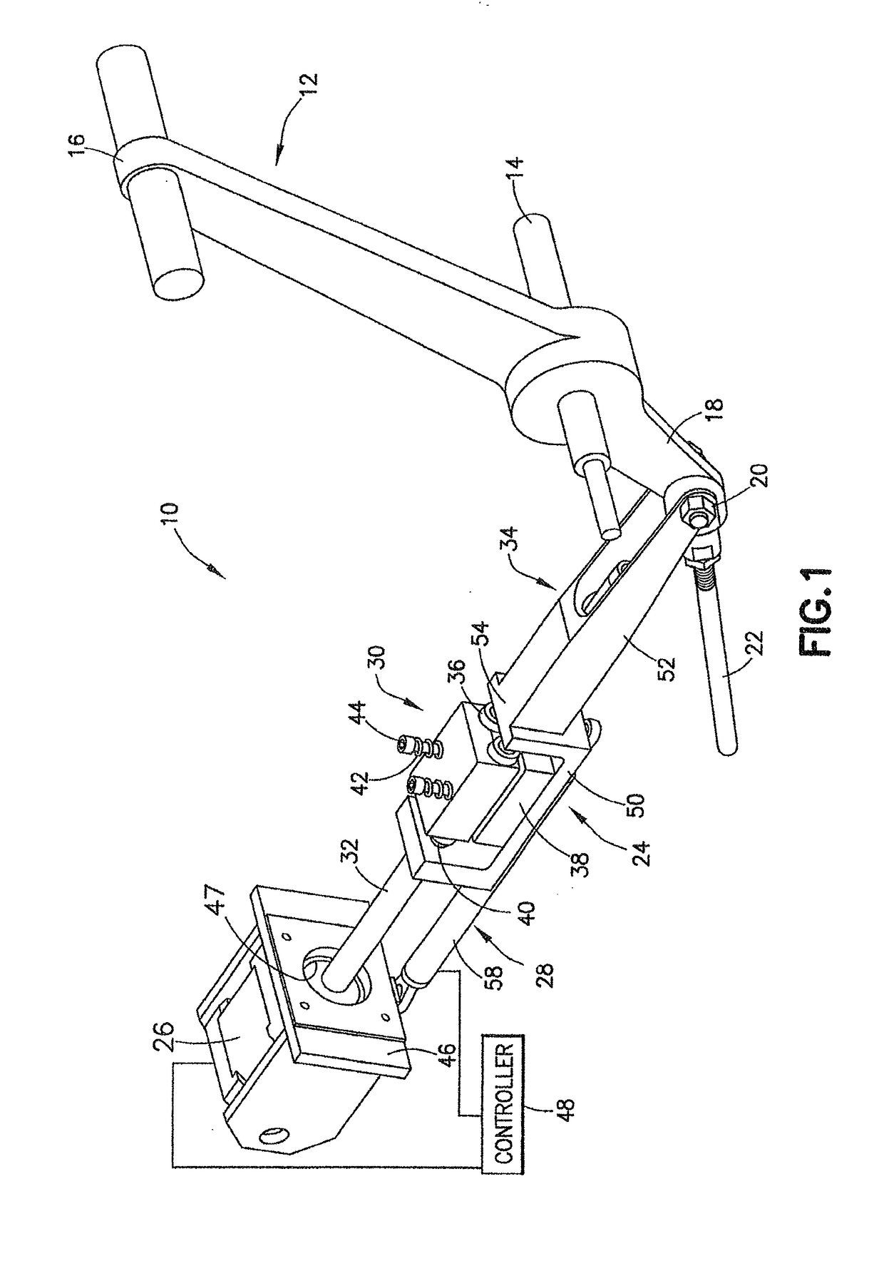
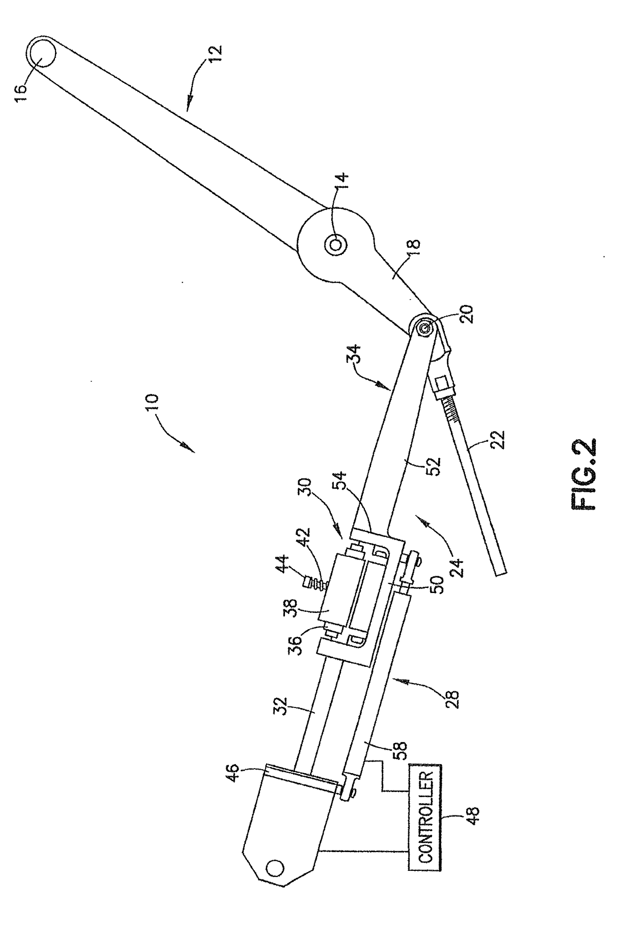
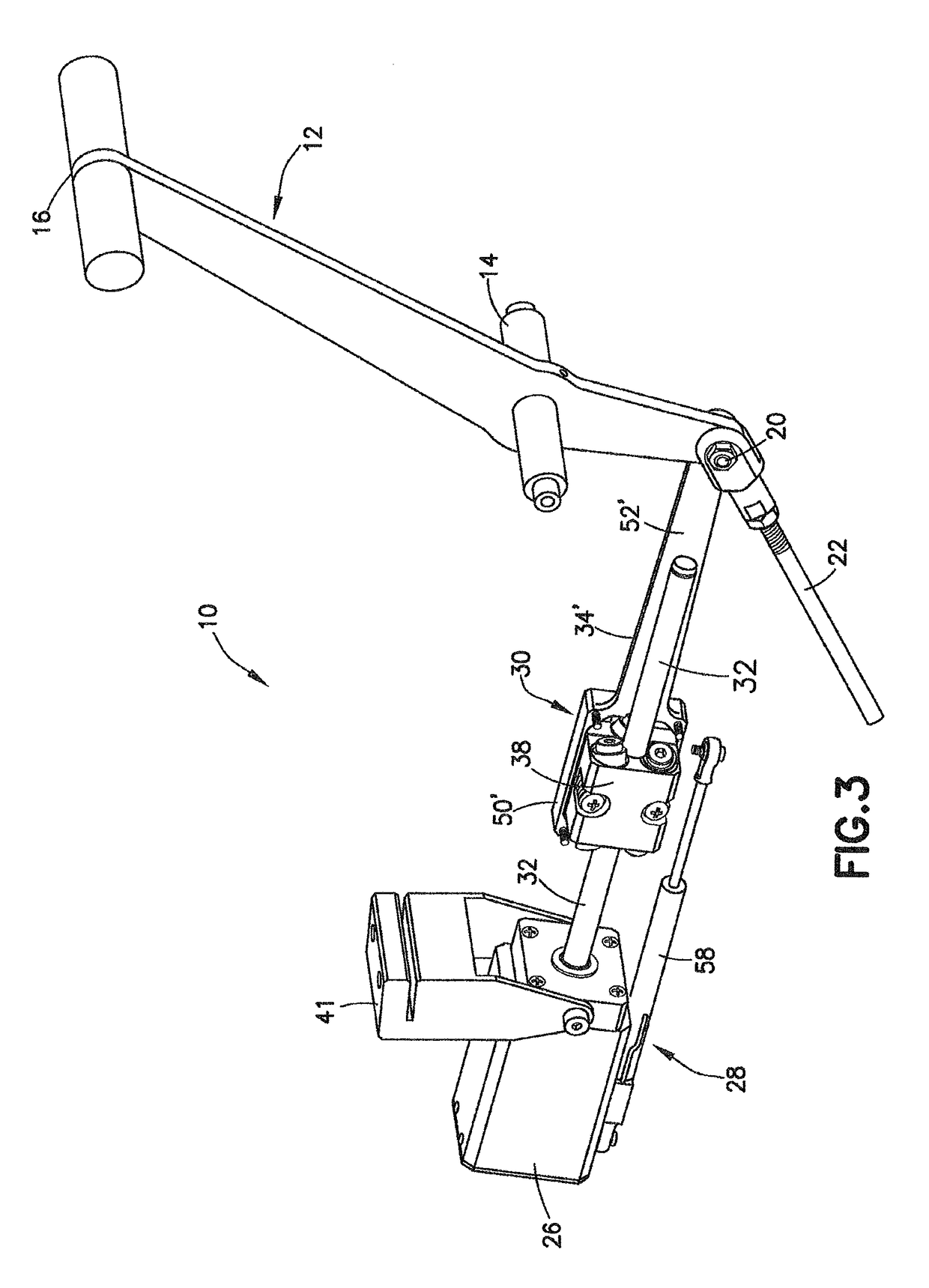
[0034]The disclosed autothrottle is configured to move an aircraft's power throttles using independent linear actuators, typically located in the throttle quadrant and commonly attached to the throttle power handle at its connection to the throttle cable. According to one aspect of the invention, an actuator functions by rotating a hardened, precision ground, and polished stainless steel shaft that carries an actuation shuttle, which is the heart of the throttle control. The actuation shuttle typically carries two sets of three precision ball bearings mounted at a rotation axis angle relative to the shaft axis. The outer races of the bearings roll on the shaft, moving the shuttle along the shaft at a rate proportional to the shaft diameter and the bearing axis angle. The shuttle's thrust is proportional the coefficient of friction between the outer race of the spring loaded ball bearings and the shaft. The shuttle moves accurately along the shaft, much like a threaded lead-screw, bu...


PUM


Abstract

An autothrottle system for an aircraft includes a motor, actuator assembly, and position sensor operatively connected between the motor and a moving portion of the actuator assembly. An electronic controller is configured to control the motor to move the actuator assembly to actuator positions based at least on position information from the position sensor to move the throttle lever to lever positions.

Description

CROSS-REFERENCE TO RELATED APPLICATION[0001]This application is a continuation-in-part of U.S. patent application Ser. No. 15 / 900,542, entitled “Precision Operator for an Aircraft autothrottle or Autopilot System With Engine Performance Adjust” filed Feb. 20, 2018, and U.S. patent application Ser. No. 15 / 554,642, entitled “Precision Operator for an Aircraft autothrottle or Autopilot System With Engine Performance Adjust” filed Aug. 30, 2017, which is a national phase of PCT Application No. PCT / US2016 / 045002, entitled “Precision Operator for an Aircraft autothrottle or Autopilot System,” filed Aug. 1, 2016, and claims priority to U.S. Provisional Patent Application No. 62 / 336,200, entitled “Precision Operator for an Aircraft autothrottle or Autopilot System,” filed May 13, 2016, and U.S. Provisional Patent Application No. 62 / 250,819, entitled “Precision Operator for an Aircraft autothrottle or Autopilot System,” filed Nov. 4, 2015; all of which are incorporated herein by reference in...

Claims


Application Information

Patent Timeline
Patent Type & Authority Applications(United States)
IPC IPC(8): B64D31/10B64D43/00F02C9/54F02C7/26G08G5/00G08G5/04G05D1/08G05D1/00G05D3/12
CPCB64D31/10B64D43/00F02C9/54F02C7/26G08G5/0008G08G5/04G05D1/0816G05D1/0072G05D3/12F05D2220/323F05D2270/20F05D2270/12F05D2270/13F05D2270/303F05D2270/093F02C9/26F05D2270/051Y02T50/60
Inventor HEDRICK, GEOFFREY S.M.
Owner INNOVATIVE SOLUTIONS & SUPPORT
Why Eureka
Try Eureka