Eureka AIR delivers breakthrough ideas for toughest innovation challenges, trusted by R&D personnel around the world.

Liquefied fuel gas system and method

Pending Publication Date: 2019-01-24
SHELL OIL CO
View PDF0 Cites 5 Cited by
  • Summary
  • Abstract
  • Description
  • Claims
  • Application Information

AI Technical Summary

Benefits of technology

The present patent discloses a system and method for managing the vapor boil-off of LNG on transport vessels. Unlike previous methods that use a vapor compressor and auxiliary consumers, this system and method subcools the LNG on the transport vessel to create a more economical, reliable, and consistent solution. This prevents weathering of the LNG and allows the quality of the LNG fuel to remain within the calorific value required by the engine manufacturer. This system and method also increases the efficiency and safety of LNG fueled transports during transfer of LNG from a discharging tank to a receiving tank by lowering the temperature of any LNG remaining in the receiving tank before transfer and thereby limiting flashing in the receiving tank during transfer. Additionally, this system and method increases the storage capacity of LNG liquid in the LNG tank by providing constant and continuous management of the LNG vapor. In summary, this technology lowers the overall cost of an LNG fuel gas supply and transfer system by eliminating additional gas consumers currently required for vapor management.

Problems solved by technology

One of the problems faced by the industry in transitioning to LNG as a fuel source is vapor management.
Otherwise, LNG boil-off cannot currently be contained in a viable or economical manner.
However, U.S. Pat. No. 5,228,295 does not solve the problem of changing gas composition due to differences in boil-off between respective fractions of the liquefied gas.
The system of U.S. Pat. No. 3,302,416 is however unsuitable for use on transports, such as vessels and trucks.
The system includes a nitrogen refrigeration circuit, which requires make-up gas to make up for lost nitrogen, which may be unacceptable in some locations due to environmental concerns or regulation.
The system of U.S. Pat. No. 3,302,416 is relatively complex, resulting in relatively high up-front investment costs (CAPEX) and increased weight of the overall equipment.
Consequently, conventional transports, such as LNG fueled vessels, have been applying gas consumers to burn the boil-off gas, which typically have limited efficiency at lower speeds of the transporter, or vapor re-liquefaction techniques, which require relatively expensive equipment.

Method used


Image

  • Liquefied fuel gas system and method
  • Liquefied fuel gas system and method
  • Liquefied fuel gas system and method

Examples


Embodiment Construction

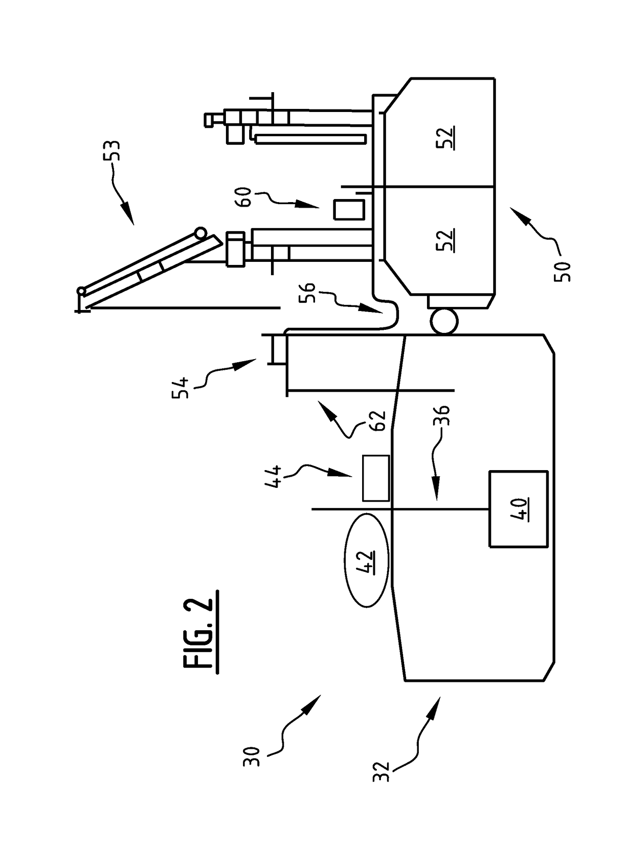
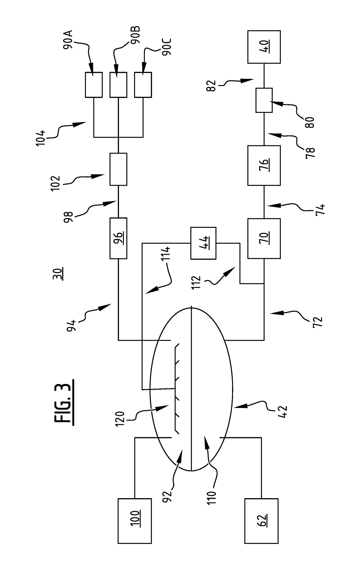
[0060]LNG is a mixture of hydrocarbon gases, all of which have varied boiling points. Under conditions of ordinary storage in a tank, from which some of the liquefied gas is allowed to boil off, fractionation of the mixture of the gases takes place in the storage tank, due to the different boiling points of the respective gases. The higher boiling point constituents vaporize less readily than those of lower boiling point, which produces a boil-off product having a lower B.t.u. content and a different composition from the liquid inventory remaining in the tank. Examples of LNG composition are provided in the table below, for exemplary compositions of “rich” LNG (i.e. LNG comprising substantial amounts of components heavier than methane, such as Ethane and Propane) and “lean” LNG (comprising modest amounts of heavier components).

[0061]Typical LNG fuel system designs incorporate vapor removal as a means to manage boil off gas (BOG) within an LNG fuel tank. This vapor removal method has...


PUM


Abstract

A method of fueling a transporter with liquefied fuel gas includes providing a transporter having a fuel gas storage tank for holding a liquefied fuel gas, a sub-cooler fluidly connected to the fuel gas storage tank, and a consumer. Liquefied fuel gas from the fuel gas storage tank is pumped into the subcooler to create subcooled liquefied fuel gas. The subcooled liquefied fuel gas may then be introduced into the fuel gas storage tank, for example by spraying into a vapor space of the fuel gas storage tank. Liquefied fuel gas is pumped from the fuel gas storage tank to provide pressurized liquefied fuel gas, the pressurized liquefied fuel gas is vaporized and the vaporized fuel gas is provided to the consumer for propelling the means of transport using the vaporized fuel gas as a fuel.

Description

TECHNICAL FIELD[0001]The present disclosure relates generally to a liquefied fuel gas system and method for fueling a transporter with liquefied fuel gas. The transporter, or means of transport, may include, for instance, a truck, train or vessel. The liquefied fuel gas may include, but is not limited to, liquefied natural gas (LNG).BACKGROUND[0002]With the number of people on our planet growing and living in cities, our roads, ports and airports are busier than ever. A range of vehicles and fuels will be needed to help meet this growing demand for transport. In the future, liquefied fuel gas, such as liquefied natural gas (LNG), could form a bigger part of the transport energy mix, alongside developments in areas such as greater vehicle efficiency, biofuels, hydrogen and electric mobility. LNG provides additional advantages in reducing CO2 emissions. Also, the use of LNG and other liquefied gasses as a fuel for transport typically also limits emissions of toxic flue gas components,...

Claims


Application Information

Patent Timeline
IPC IPC(8): F17C7/04F17C1/00F17C13/00
CPCF17C7/04F17C1/005F17C13/004F17C2221/033F17C2223/0161F17C2223/033F17C2223/046F17C2225/0169F17C2225/033F17C2227/0135F17C2227/0157F17C2227/0178F17C2227/0355F17C2227/0393F17C2250/0439F17C2270/0105F17C2270/0171F17C1/00F17C2225/044F17C2227/039F17C2250/0452F17C2250/0456F17C2250/0636F17C2260/056F17C2265/035F17C2265/066F17C2270/0173F17C2250/0652F17C3/025
Inventor HUTCHINS, WILLIAM RALPHHARTMAN, SCOTT JAMES SIEBERT
Owner SHELL OIL CO
Why Eureka
Eureka Blog
Learn More