Fishbones, electric heaters & proppant to produce oil

Active Publication Date: 2019-01-17
CONOCOPHILLIPS CO
View PDF2 Cites 4 Cited by
  • Summary
  • Abstract
  • Description
  • Claims
  • Application Information

AI Technical Summary

Benefits of technology

The patent describes a method of improving oil recovery in heavy oils by combining the SAGD concept with a fishbone well architecture. This method involves replacing conventional wellbores with fishbone wells that provide overlapping coverage of the pay zone between the injector and producer wells. The arrangement of lateral wells is designed to bridge the steam gaps and optimize performance. The use of this well configuration significantly reduced or even eliminated the startup time needed to bring the well-pairs into fluid communication, saving time and money. The method also involves using downhole electrical heaters to heat the reservoir and heavy oil contained therein, improving oil recovery and production rates. The use of this method is less viable in areas where high temperature and pressure conditions are associated with high risk and cost. The ideal thermally conductive proppant should be inert to the oil, have good mechanical strength, and be inexpensive. The patent also describes the option of providing overlapping laterals or using only producers with lateral wells, which can still adequately cover the reservoir between adjacent main wellbores.

Problems solved by technology

Although quite successful, SAGD does require enormous amounts of water in order to generate a barrel of oil.
In addition to using a precious resource, additional costs are added to convert those barrels of water to high quality steam for downhole injection.
Therefore, any technology that can reduce water or steam consumption has the potential to have significant positive environmental and cost impacts.
Another problem with steam-based methods is that they may be less appropriate for use in the Artic, where injecting large amounts of steam for months and years on end has high potential to melt the permafrost, allowing pad equipment and wells to sink, with potentially catastrophic consequences.
Indeed, the media is already reporting the slow sinking of Artic cities, and cracking and collapsing homes are a growing problem in cities such as Norilsk in northern Russia.
1) Higher Production. In the cases where thin pools are targeted, vertical wells provide minimal contact with the reservoir, which causes lower production. Drilling several laterals in thin reservoirs and increasing contact improves recovery. Slanted laterals can be of particular benefit in thin, stacked pay zones.
2) Decreased Water / Gas Coning. By increasing the length of “wellbore” in a horizontal strata, the inflow flux around the wellbore can be reduced. This allows a higher withdrawal rate with less pressure gradient around the producer. Coning is aggravated by pressure gradients that exceed the gravity forces that stabilize fluid contacts (oil / water or gas / water), so that coning is minimized with the use of multilaterals, which minimize the pressure gradient.
3) Improved sweep efficiency. By using multilateral wells, the sweep efficiency may be improved, and / or the recovery may be increased due to the additional area covered by the laterals.
Drilling several laterals in a single well may result in time and cost saving in comparison with drilling several separate wells in the reservoir.
Although an improvement, the multilateral well methods have disadvantages too.
One disadvantage is that fishbone wells are more complex to drill and clean up.
Indeed, some estimate that multilaterals cost about 20% more to drill and complete than conventional slotted liner wells.
Another disadvantage is increased risk of accident or damage, due to the complexity of the operations and tools.
Sand control can also be difficult.
Therefore, the sand control from the branches is not easy to perform.
There is also increased difficulty in modeling and prediction due to the sophisticated architecture of multilateral wells.
Another area of uncertainty with the fishbone concept is stability—whether the ribs will establish and maintain communication with the offset steam chambers, or will the open-hole ribs collapse early and block flow.
At this point the open-hole rib could easily collapse.
Yet another uncertainty with many ribs along a fishbone producer of this type is that one rib may tend to develop preferentially at the expense of all the other ribs leading to very poor conformance and poor results.

Method used


Image

  • Fishbones, electric heaters & proppant to produce oil
  • Fishbones, electric heaters & proppant to produce oil
  • Fishbones, electric heaters & proppant to produce oil

Examples


Embodiment Construction

[0115]The following is a detailed description of the preferred method of the present invention. It should be understood that the inventive features and concepts may be manifested in other arrangements and that the scope of the invention is not limited to the embodiments described or illustrated. The scope of the invention is intended to only be limited by the scope of the claims that are appended hereto.

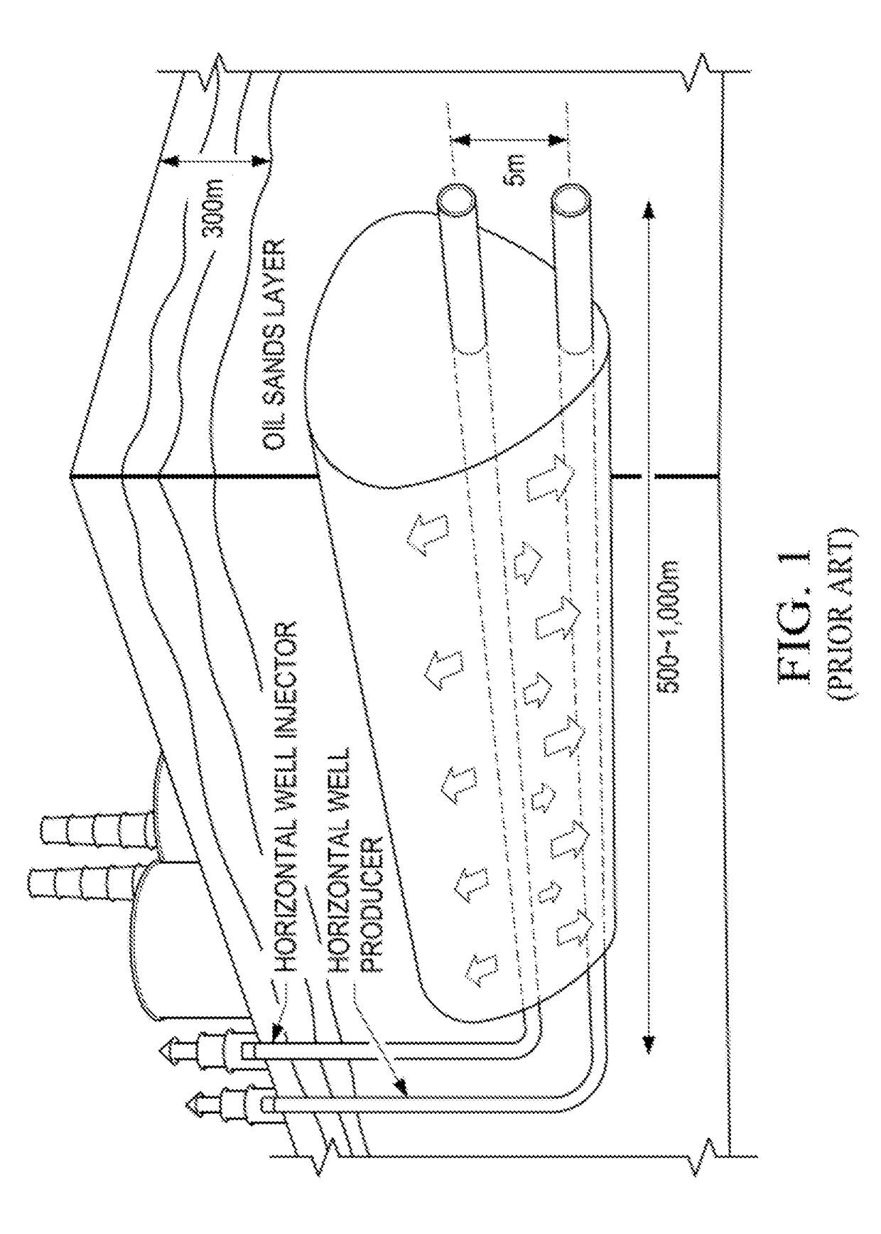
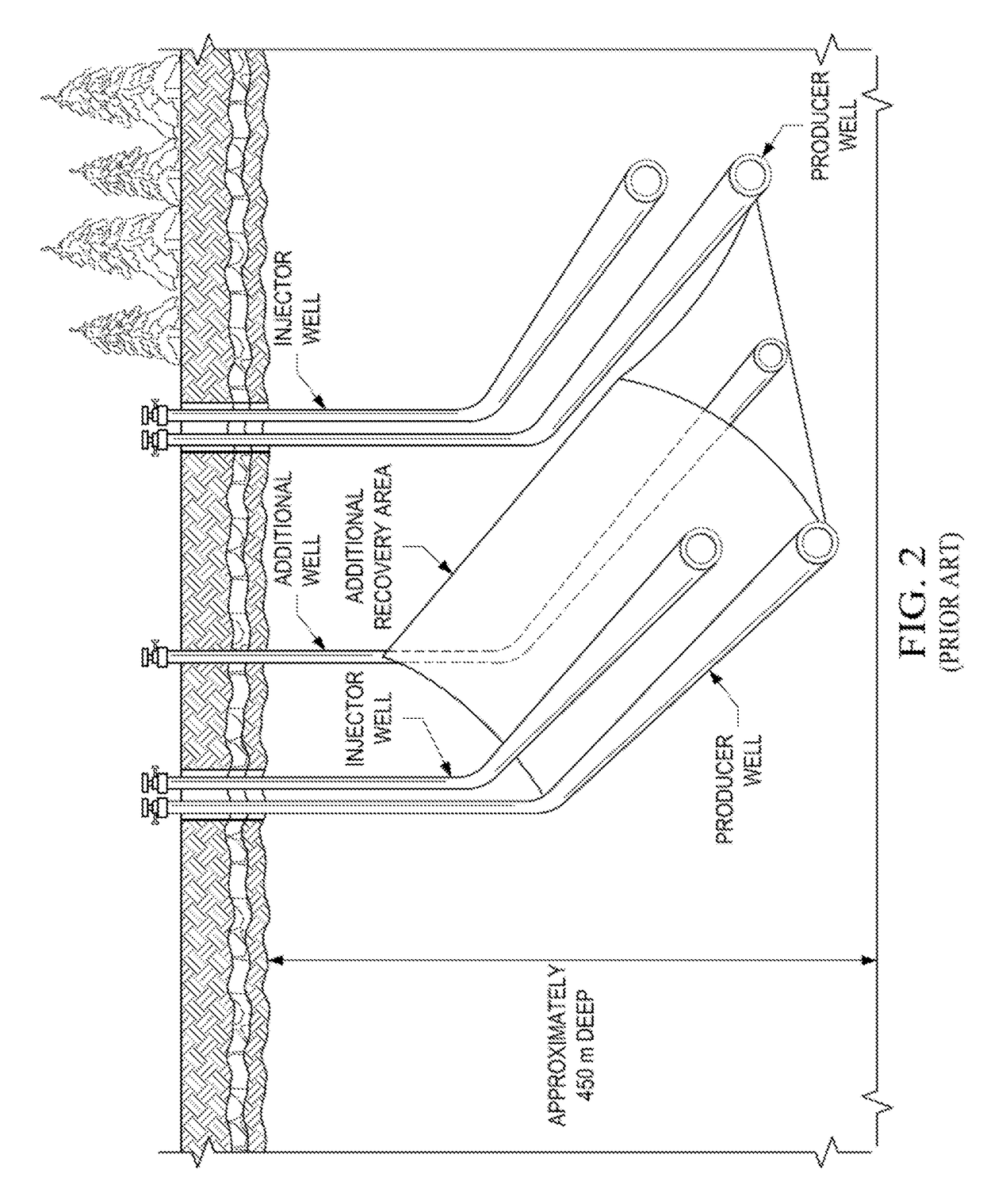
[0116]The present invention provides a novel well configuration for electrically heated production of heavy oils using a thermally conductive proppant for heat conduction and lateral wells for play coverage.

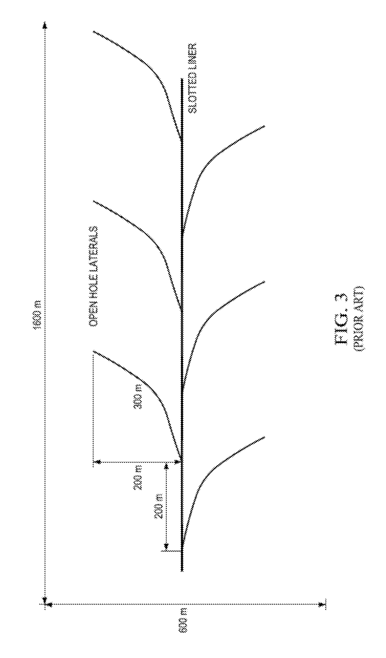
[0117]Methods and well configurations are proposed to drill open-hole fishbone or multilateral well bores and use downhole electrical heating in the main wellbores to produce oil from bitumen, oil sands or other heavy oil reservoirs. The fishbone or multilateral wells are filled with thermally conductive material, such as bauxite particles, so that the heat provided from downhole ...


PUM

PropertyMeasurementUnit
Lengthaaaaaaaaaa
Lengthaaaaaaaaaa
Fractionaaaaaaaaaa

Abstract

The present disclosure relates to a particularly effective well configuration that can be used for heat based oil recovery methods. Fishbone multilateral wells are combined with inline electric heaters and a thermally conductive proppant. Preferably, an array of overlapping fishbone wells cover the pay, allowing more complete production of the pay, and the use of the proppants prevents the open-hole fishbone laterals from collapsing. These methods can be applied in variety of configurations, including traditional vertically spaced well-pairs, laterally spaced well-pairs, producers only, and combinations thereof.

Description

PRIORITY CLAIM[0001]This application claims priority to U.S. Ser. No. 62 / 523,614, filed Jun. 22, 2017, and incorporated by reference in its entirety for all purposes.FIELD OF THE INVENTION[0002]This invention relates generally to well configurations that can advantageously produce oil. In particular, electric heaters are deployed in the main or motherbore of a horizontal well and open-hole fishbones drilled off of the motherbore are filled with thermally conductive proppants. The heaters heat the region around the motherbore and the proppants, which are highly conductive, transmit heat to the reservoir to enhance the production of heavy oil. In Arctic environments, the use of downhole heaters avoids high heat levels at the surface, thus avoiding melting of the permafrost, and potential catastrophic results.BACKGROUND OF THE INVENTION[0003]Many countries in the world have large heavy oil deposits, including the United States, Russia, and the Middle East, but the world's largest depos...

Claims


Application Information

Patent Timeline
IPC IPC(8): E21B43/24C09K8/592C09K8/66C09K8/80E21B43/14E21B43/30
CPCE21B43/2401C09K8/592C09K8/665C09K8/80C09K2208/00E21B43/305C04B35/64C04B2235/3218C04B2235/9607E21B43/14
Inventor WHEELER, T. J.GAMAGE, SILUNI L.MENARD, WENDELL P.
Owner CONOCOPHILLIPS CO
Why Eureka
Try Eureka