Machine tool and cutting method

a cutting method and machine tool technology, applied in the direction of tools, auxiliary equipment, tool holders, etc., can solve the problem of difficulty in high-adjustable machined inclined surfaces

Inactive Publication Date: 2019-01-03
MURATA MASCH LTD
View PDF0 Cites 0 Cited by
  • Summary
  • Abstract
  • Description
  • Claims
  • Application Information

AI Technical Summary

Benefits of technology

The patent describes a cutting method for machining inclined surfaces using a cutting tool that is held in a perpendicular position to the surface and rotated around a Y-axis. The method includes holding the workpiece on a main spindle and rotating the tool post to cause the cutting tool to correspond to the inclined surface. The direction of the thrust force acting on the cutting tool is determined and the inclination of the cutting tool is suppressed, allowing for high-accuracy machining of the inclined surface. The guide surface of the Y-direction guide is perpendicular to the direction of the thrust force, ensuring accurate machining of the inclined surface. The main spindle and the cutting tool can be moved in the Y- and Z-directions without changing the X-direction, simplifying movement control and allowing for more accurate machining. The inclination angle of the inclined surface can be measured and adjusted to form a desired angle, improving surface roughness and machining accuracy. The method allows for high-accuracy machining of inclined surfaces and simplifies feeding control of the cutting tool.

Problems solved by technology

If the cutting tool is inclined by the thrust force, it would be difficult to machine the inclined surface with high accuracy.

Method used


Image

  • Machine tool and cutting method
  • Machine tool and cutting method
  • Machine tool and cutting method

Examples


first example

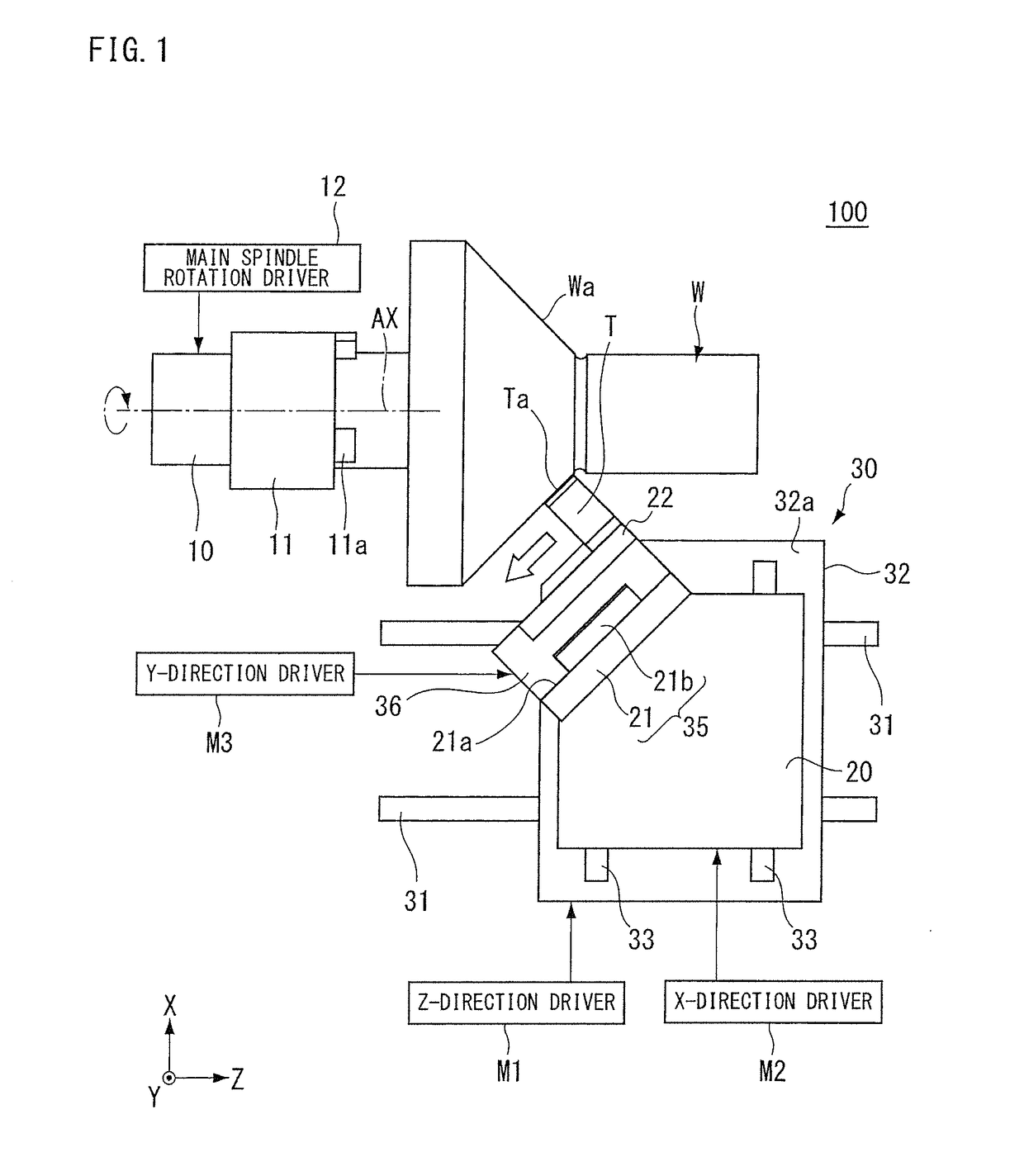
[0058]A machine tool 100 of a first example will be described. FIG. 1 is a drawing showing the machine tool 100 of the first example. The machine tool 100 is a lathe that cuts a workpiece W having an inclined surface Wa, and FIG. 1 shows a major part of the lathe. In FIG. 1, the positive Y-side of the machine tool 100 is the front side thereof, and the negative Y-side thereof is the back side thereof. The positive and negative Z-sides of the machine tool 100 are the lateral sides thereof, and the Z-direction represents the left-right direction of the machine tool 100. As shown in FIG. 1, the machine tool 100 includes a main spindle 10, a tool post 20, and a mover 30. The main spindle 10, the tool post 20, and the mover 30 are disposed, for example, in a frame (not shown) serving as the cabinet of the machine tool 100.

[0059]While the main spindle 10 is disposed in the frame (not shown), it may be disposed to be movable in the Z-direction, the X-direction, the Y-direction and / or the l...

second example

[0081]A machine tool 200 of a second example will be described. In this example, elements similar to those of the first example are given the same reference signs, and description thereof will be simplified or omitted. FIG. 4 is a drawing showing the machine tool 200 of the second example. As in the first example, the machine tool 200 is a lathe that cuts a workpiece W having an inclined surface Wa, and FIG. 4 shows a major part of the lathe.

[0082]As shown in FIG. 4, the machine tool 200 includes a main spindle 10, a tool post 120, and a mover 130. The main spindle 10, the tool post 120, and the mover 130 are disposed, for example, in a frame (not shown) serving as the cabinet of the machine tool 200. The machine tool 200 is set such that the axis AX of the main spindle 10 is inclined in the negative θY-direction with respect to a horizontal plane by an angle β. For this reason, in the description of the second example, a direction inclined in the positive θY-direction with respect ...

third example

[0100]A machine tool 300 of a third example will be described. In the third example, elements similar to those of the first and second examples are given the same reference signs, and description thereof will be simplified or omitted. FIG. 7 is a drawing showing the machine tool 300 of the third example. As in the first and second examples, the machine tool 300 is a lathe that cuts a workpiece W having an inclined surface Wa, and FIG. 7 shows a major part of the lathe.

[0101]In the second example, the cutting tool T (tool post 120) is rotated in the θY-direction by the rotary table 137. In the third example, the direction of a cutting edge Ta is aligned with the direction of an inclined surface Wa by rotating a main spindle 10 in the θY-direction (around a θY-axis). A coordinate system in FIG. 7 corresponds to the coordinate system shown in FIGS. 4 to 6.

[0102]The machine tool 300 includes the main spindle 10, a tool post 120, a mover 230, and an around-Y-axis rotation driver 212. As ...


PUM

PropertyMeasurementUnit
Forceaaaaaaaaaa
Angleaaaaaaaaaa

Abstract

A machine tool for cutting a workpiece having an inclined surface includes a main spindle that rotates while holding the workpiece, a tool post that holds a cutting tool to cut the inclined surface of the workpiece, a mover that relatively moves the workpiece and the cutting tool in a direction including at least a Y-direction perpendicular to both a Z-direction parallel to an axis of the main spindle and an X-direction that is perpendicular to the Z-direction and determines the amount of cutting of the workpiece. The mover includes a Y-direction guide disposed on the tool post, the Y-direction guide guiding movement of the cutting tool in the Y-direction, and the Y-direction guide has a guide surface along a surface perpendicular to a direction of a thrust force that occurs when cutting the inclined surface using the cutting tool.

Description

TECHNICAL FIELD[0001]This disclosure relates to a machine tool and a cutting method.BACKGROUND[0002]A lathe, which is a machine tool, holds a workpiece to be machined, on a rotating spindle and performs cutting or the like on the workpiece using a cutting tool while rotating the workpiece. Examples of known machining methods using a lathe include a machining method that involves cutting the inclined surface of a workpiece while feeding a cutting tool in the direction of a tangent to the workpiece (a direction crossing a rotating spindle) as discussed in International Publication No. 2015-079836.[0003]A lathe disclosed in WO '836 cuts the inclined surface of the workpiece by feeding the cutting tool while maintaining inclination of the cutting tool with respect to the inclined surface. However, when cutting the inclined surface while feeding the cutting tool, the cutting tool receives a thrust force in a direction perpendicular to the inclined surface. If the cutting tool is inclined...

Claims


Application Information

Patent Timeline
IPC IPC(8): B23B5/38B23B29/32B23B25/06
CPCB23B5/38B23B29/32B23B25/06B23Q2220/002B23Q2717/003B23B1/00
Inventor ISHIHARA, TADASHI
Owner MURATA MASCH LTD
Why Eureka
Try Eureka