
Lighting and sound system

Active Publication Date: 2018-12-06
ZUMA ARRAY LTD
View PDF6 Cites 19 Cited by
  • Summary
  • Abstract
  • Description
  • Claims
  • Application Information

AI Technical Summary

Benefits of technology

This patent is about a system that allows users to control light and loudspeaker devices using their voice commands. This eliminates the need for dedicated remotes or external applications and makes the system more flexible and easy to use. Additionally, the system can integrate with existing systems in the user's house by utilizing satellite devices manufactured by third parties such as smart bulbs and wireless speakers. The technical effect of this patent is improved convenience and flexibility for users while simplifying the way they control the light and loudspeaker devices in their house.

Problems solved by technology

This additional wiring can be expensive and time consuming to install.
However, installation of these panels can require additional wiring, again leading to increased cost and complexity in installation.
Thus, in practice, control of such systems may be restricted to a limited number of users.
Such systems are typically very expensive, and often require a significant amount of installation work to be carried out on walls and / or ceilings.
There are also particular challenges with the control and distribution of sound within a building; for example, permitting different content to be supplied to different rooms may require multiple separate controllers and receivers within a single building.
With a system having individual devices containing both a light and a loudspeaker system control is complicated still further.
Achieving such individual, independent control of each separate combined light and loudspeaker device becomes ever more challenging as the number and distribution of devices increases, resulting in potentially significant installation costs due to rewiring, wall and ceiling modifications, etc.
However, the quality of the light, sound produced by this system is not sufficient for high-end applications.
Moreover, as a result of issues relating to the management of power and heat in these devices, the devices can only operate at low power.
This quality of this light may not be suitable for certain applications, such as task lighting.
As with the system described in US 2011 / 151782, the devices can only operate at low power due to heat management issues arising from packaging a transformer and electronics in the bulb.
This system further has the power and heat management drawbacks of being packaged in a bulb and using a standard bulb socket described above.
Combined loudspeaker and light devices in the form of bulbs for standard light fittings are limited in physical size and hence audio volume.
Moreover, the light or sound emitted by the bulb may be obstructed by the light fitting.

Method used


Image

  • Lighting and sound system
  • Lighting and sound system
  • Lighting and sound system

Examples


Embodiment Construction

Device

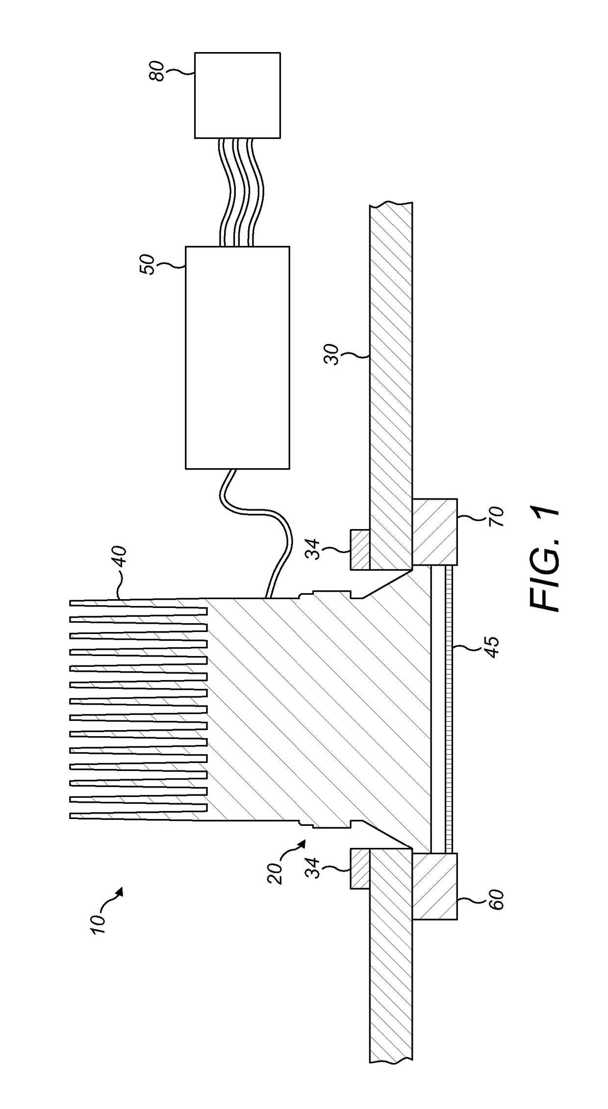
[0073]FIG. 1 shows a schematic diagram of a lighting and sound device 10 that includes a light source, loudspeaker and user input detector embodying the present invention. The lighting and sound device 10 comprises a loudspeaker driver 20, which may be positioned within an aperture formed in a ceiling 30 such that the device 10 is sub-flush with the ceiling 30. The loudspeaker driver 20 may be securely mounted to the ceiling 30 via a fixing 34. The fixing 34 can be damped to prevent vibration transmission to the ceiling 30. The fixing 34 can also be made of an intumescent material to serve as a fire barrier.

[0074]The system of the present invention is installed in existing lighting space in the ceiling void. Therefore, in contrast to prior art systems, this system is effectively invisible as the devices are fitted out of eye level and fit within the footprint of existing in-ceiling luminaries. Moreover, the devices can be easily retrofitted to the existing infrastructure of th...


PUM


Abstract

A method of controlling a lighting and sound system comprising a controller and a plurality of lighting and sound devices 10 is provided. Each lighting and sound device 10 includes a light, a loudspeaker and a microphone 380. The method comprises receiving an audio instruction from a first user of the system at the microphone of a first device of the plurality of devices. The method further comprises processing the received audio instruction. The method further comprises transmitting the instruction from the first device to the controller. The method further comprises executing an action based upon the processed audio instruction.

Description

FIELD OF THE INVENTION[0001]This invention relates to a lighting and sound system, in particular having a plurality of combined light and sound devices that may be controlled using voice commands.BACKGROUND OF THE INVENTION[0002]Integrated light and loudspeaker systems are known in the art. For example, US-A-2007 / 222631 describes a system having a plurality of devices, each of which is capable of producing both light and sound. The system of US-A-2007 / 222631 is arranged to receive an audio signal wirelessly from a sound source, and includes a repeater that sends the received audio signal to others of the devices in the system.[0003]In prior art systems such as the one mentioned above, there are differing power requirements for the components within the unit. Mains power at a higher voltage therefore has to be reduced with a transformer or power convertor placed in a junction box. Lower voltage power to the lighting elements is brought from the electrical junction box to the LEDs. Th...

Claims


Application Information

Patent Timeline
IPC IPC(8): G10L15/22G10L21/0232G10L15/08G06F3/16H03G5/16H05B37/02F21V33/00F21V29/70
CPCG10L15/22G10L21/0232G10L15/08G06F3/165H03G5/165H05B37/0236F21V33/0056F21V29/70G10L2021/02082G10L2015/223G10L2015/088F21Y2115/10F21V23/0464F21V23/0457F21V23/0471H04R1/028F21V23/045Y02B20/40H05B47/12
Inventor COOK, SUSANLELLY, STEVENWARREN, MORTENHWANG, SEONG MINHOGGARTH, MARCUS
Owner ZUMA ARRAY LTD
Learn More