Electronically pressure-controllable braking system and methods for controlling an electronically pressure-controllable braking system

a technology of electronic pressure control and braking system, which is applied in the direction of braking system, asr control system, braking components, etc., can solve the problems of increased construction costs, increased space requirements, and inability to assume passenger emergency situations, so as to reduce load and cost, the effect of reducing costs

Active Publication Date: 2018-11-22
ROBERT BOSCH GMBH
View PDF6 Cites 4 Cited by
  • Summary
  • Abstract
  • Description
  • Claims
  • Application Information

AI Technical Summary

Benefits of technology

The patent describes a braking system that uses a non-return valve to prevent brake pressure from dissipating through another valve. This prevents the brakes from being forced to release when not needed. The system is designed to be simple and can be easily assembled from existing components. It also eliminates the need for a master brake cylinder and brake pedal, making it safer and reducing the likelihood of malfunctions. The use of identical subunits with mutual redundancy reduces wear and tear and lowers costs. Overall, the system is more efficient and reliable.

Problems solved by technology

In autonomously driving motor vehicles, however, the attention of the passengers during the driving operation is not ensured so that an intervention of a passenger in emergency situations cannot be assumed.
Compared to conventional braking systems, redundant braking systems require a markedly greater effort of construction and accordingly have a greater space requirement and moreover entail higher costs.

Method used


Image

  • Electronically pressure-controllable braking system and methods for controlling an electronically pressure-controllable braking system
  • Electronically pressure-controllable braking system and methods for controlling an electronically pressure-controllable braking system
  • Electronically pressure-controllable braking system and methods for controlling an electronically pressure-controllable braking system

Examples


Embodiment Construction

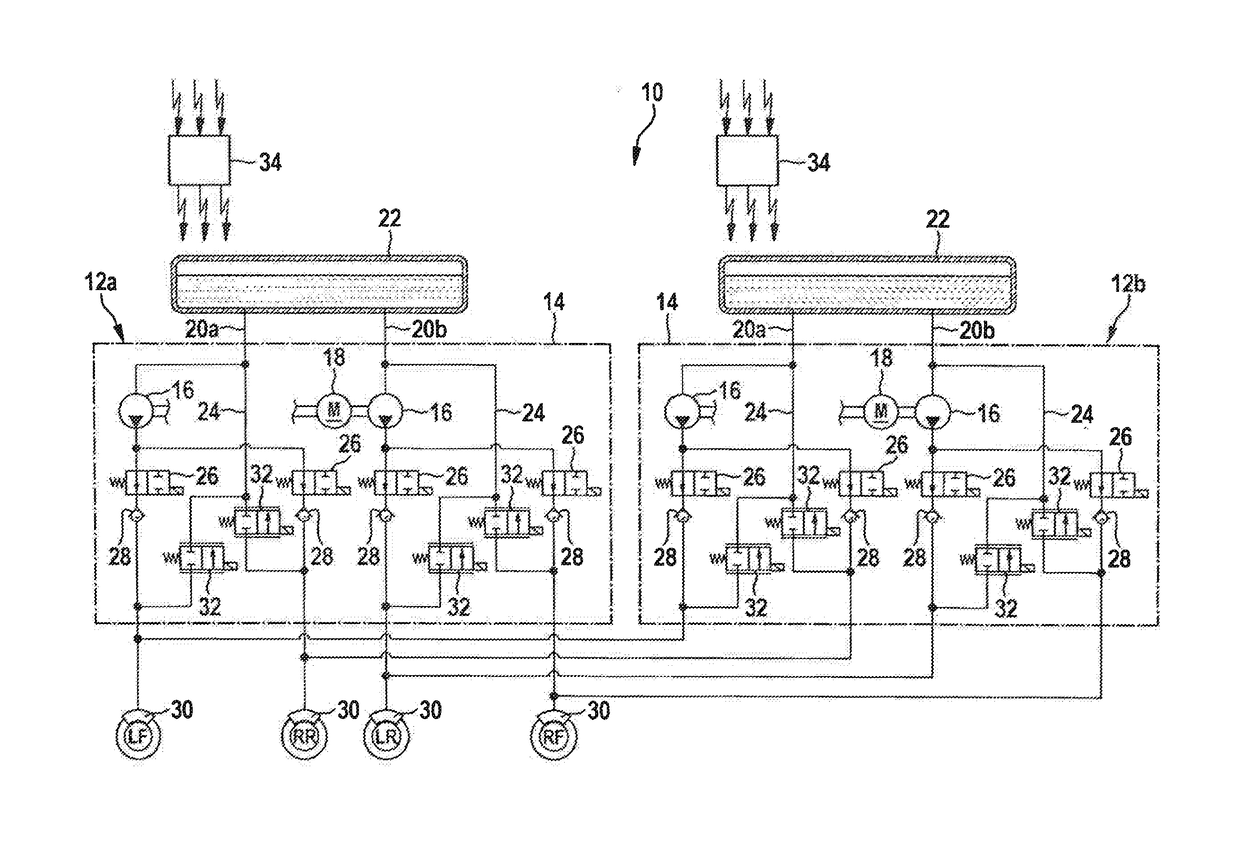
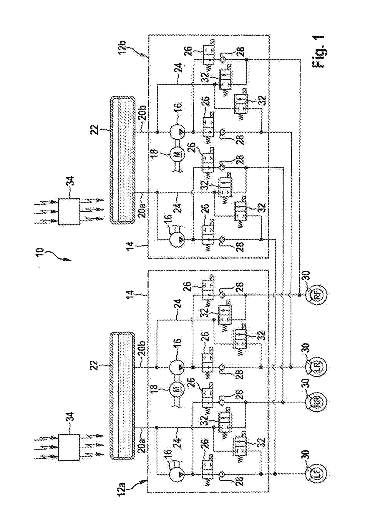
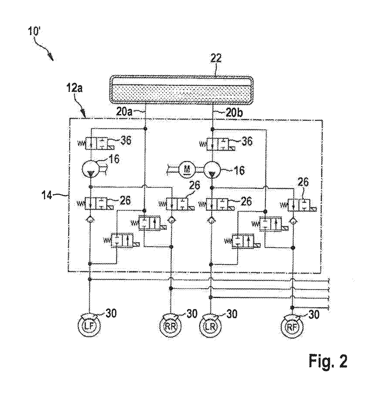
[0018]The electronically pressure-controllable braking system 10 is made up of a pressure medium unit 12, which is subdivided into a total of two subunits 12a, 12b. Both subunits 12a, 12b are identically constructed so that the further explanations can be limited to subunit 12a.

[0019]Subunit 12a comprises a so-called pump housing 14, which is equipped with electronically controllable, pressure medium-controlling components. Two pumps 16 shall be mentioned in this respect, which are operable by a common drive motor 18. Pumps 16 may alternatively be a single-piston pump or a multi-piston pump, or even a gear pump or the like. Each pump 16 supplies an associated brake circuit 20a, 20b with pressure medium and for this purpose is in direct connection on its intake side with an externally situated reservoir 22, which is in contact with pump housing 14, and parallel thereto with a return line 24 of brake circuit 20. A pressure side of pump 16 is connected respectively via one intake valv...


PUM


Abstract

An electronically pressure-controllable braking system and methods for controlling an electronically pressure-controllable braking system. Each wheel brake of the braking system is connected respectively to at least two brake circuits, pump units and valve devices of one brake circuit are operable respectively independently of the pump units and the valve devices of the respective other brake circuit. This provides a cost-effectively and compactly designed redundant braking system, which is suitable for use in autonomously, i.e., driverlessly drivable, motor vehicles.

Description

CROSS REFERENCE[0001]The present application claims the benefit under 35 U.S.C. § 119 of German Patent Application No. DE 102017208351.4 filed on May 18, 2017, and German Patent Application No. DE 102018205957.8 filed on Apr. 19, 2018, which are each expressly incorporated herein by reference in its entirety.BACKGROUND INFORMATION[0002]The present invention relates to an electronically pressure-controllable braking system, in particular for an autonomously driving motor vehicle, and to methods for controlling an electronically pressure-controllable braking system.[0003]Electronically pressure-controllable braking systems of conventional motor vehicles are equipped with a pressure medium unit for setting and controlling wheel-specific brake pressures on wheel brakes, which are respectively associated with one of several brake circuits of the braking system and are connected to the pressure medium unit. For this purpose, the pressure medium unit has one electronically controllable pum...

Claims


Application Information

Patent Timeline
Patent Type & Authority Applications(United States)
IPC IPC(8): B60T8/17B60T7/12B60T8/34B60T13/18B60T8/50B60T13/64B60T13/66
CPCB60T8/17B60T7/12B60T8/345B60T13/18B60T8/50B60T13/64B60T13/66B60T2270/10B60T2270/20B60T2270/306B60T8/326B60T8/348B60T2201/03B60T2270/413
Inventor PALOMBA, FANNYBELING, HORSTFRIEDRICH, THOMASKOCOUREK, VACLAV
Owner ROBERT BOSCH GMBH
Why Eureka
Try Eureka