Eureka AIR delivers breakthrough ideas for toughest innovation challenges, trusted by R&D personnel around the world.

Surgical power drill including a measuring unit suitable for bone screw length determination

a power drill and measuring unit technology, applied in the field of surgical power drills, can solve the problems of cumbersome handling for surgeons, complex electrical and mechanical measuring systems, and rapid decrease of electrical current drawn by motors, and achieve the effect of simple configuration and bone screw length estimation

Active Publication Date: 2018-11-15
SYNTHES GMBH
View PDF0 Cites 266 Cited by
  • Summary
  • Abstract
  • Description
  • Claims
  • Application Information

AI Technical Summary

Benefits of technology

The invention is a surgical power drill that has a measuring device to estimate the length of bone screws during drilling. The device is easy to use and requires no additional information besides the drilling characteristics. This simplifies the process of preparing for surgery and reduces the time it takes to complete the procedure.

Problems solved by technology

When the drill bit bores through the distal side of the bone, the frictional force generated by the drill bit rubbing against the bone suddenly decreases resulting in a rapid decrease of the electrical current drawn by motor.
A drawback of this known surgical drill is that it includes two different measuring devices, a first one for detecting when the drill bit exits a bone by measurement of the electric current drawn by the motor and a second one for determining the drilling depth resulting in a complex electrical and mechanical measuring system.
A drawback of this known surgical power drill is that due to the rod connecting the displaceable tip to the sensor of the measuring device the measuring device has an unwieldy configuration resulting in a cumbersome handling for the surgeon.
Furthermore, the rod impedes the view of the surgeon on the operation site.

Method used


Image

  • Surgical power drill including a measuring unit suitable for bone screw length determination
  • Surgical power drill including a measuring unit suitable for bone screw length determination
  • Surgical power drill including a measuring unit suitable for bone screw length determination

Examples


Embodiment Construction

Definitions

[0087]The following definitions of terms and wordings currently used describe the exact meaning thereof as they are used throughout the present specification:

Position x of the Cutting Tip of the Drill Bit Relative to a Surface of a Bone or of an Implant:

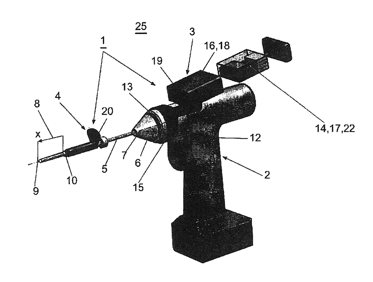
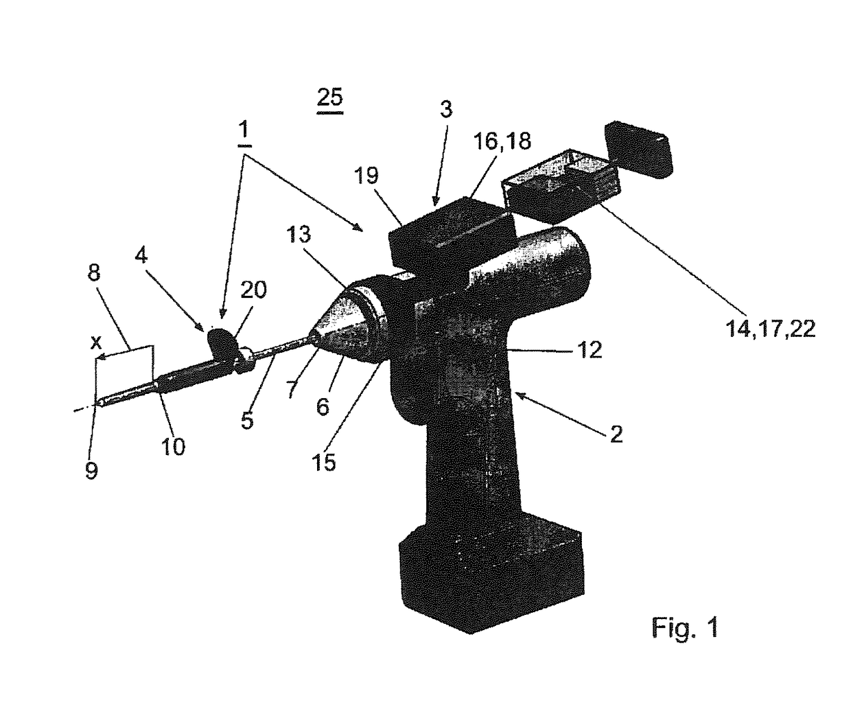
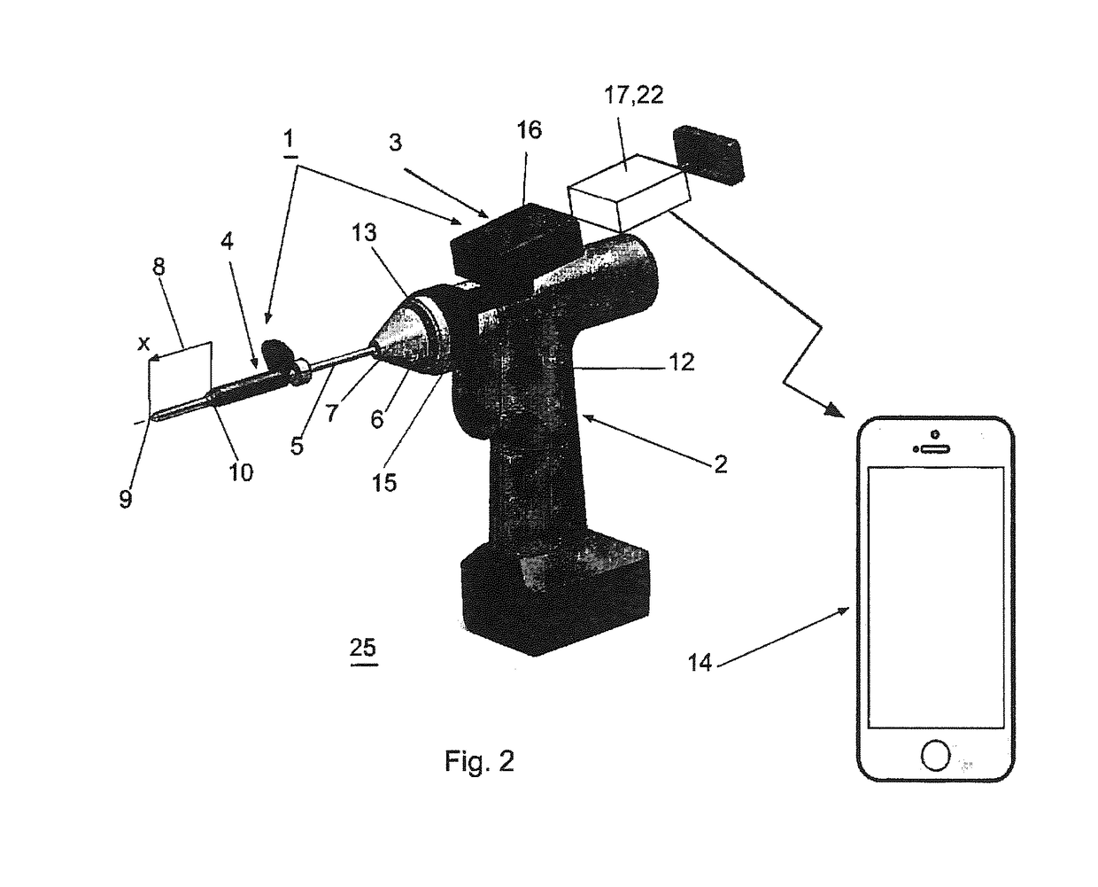
[0088]During a drilling process the distance x covered by the housing 12 in the direction of the longitudinal axis 7 of the spindle 13 and relative to a surface of a bone or of an implant 26 is related with the position x of the cutting tip 9 of the drill bit 5 relative to a surface of a bone or of an implant 26 in the drilling direction because the drill bit 5 is firmly fixed in the chuck 6 of the surgical power drill 2 and positioned at the beginning of the drilling process as described in detail below.

Differentiator:

[0089]The processing unit 14 of the device according to the invention can be configured by using digital technique or by using analog technique.

[0090]In the case that the processing unit 14 (FIGS. 1-4) is co...


PUM


Abstract

A device (25) for drilling holes in bone and configured to determine bone screw length, the device (25) including a surgical power drill (2) comprising: a) a housing (12) and; b) a measuring device (1) releasably attached or fixed to the housing (12), wherein the measuring device (1) is configured to measure the distance (x) covered by the housing (12) in the direction of the longitudinal axis (7) and relative to a surface of an implant (26) or a bone during a drilling process, wherein the measuring device (1) comprises a processing unit (14) to record the distance (x) covered with respect to time; the processing unit (14) comprises one or more differentiators to determine at least the first and second derivatives of the distance (x) covered with respect to time; and the processing unit (14) further comprises a peak detector to analyze one or more peaks occurring in the graph of the highest derivative with respect to time, and wherein the measuring device (1) comprises a laser device or an ultrasound position sensor for displacement assessment.

Description

BACKGROUND OF THE INVENTION1. Field of the Invention[0001]The invention relates to a surgical power drill including a measuring unit suitable for bone screw length determination according to the preamble of independent claim 1, to a device including a surgical power drill and a measuring unit suitable for bone screw length determination according to the preamble of independent claim 2 and to a method for bone screw length estimation from drilling characteristics using the surgical power drill according to the preamble of claim 49.[0002]From clinical observations one problem in orthopedic and trauma surgery is the determination of the required screw lengths for e.g. bi-cortical screw placement before inserting a screw into a bone fragment. Current mechanical depths gauges are rather inaccurate, unreliable and difficult to handle resulting in:[0003]prolonged surgery time;[0004]insertion of too long screws resulting in soft tissue irritation, pain and re-operation;[0005]insertion of to...

Claims


Application Information

Patent Timeline
Patent Type & Authority Applications(United States)
IPC IPC(8): A61B17/16A61B17/17A61B90/00
CPCA61B17/1622A61B17/1728A61B90/06A61B17/1615A61B17/1633A61B2090/061A61B2090/062A61B17/1626
Inventor WINDOLF, MARKUSSCHUETZ, MICHAEL
Owner SYNTHES GMBH
Why Eureka
Eureka Blog
Learn More