
Hydrogen recovery method

a technology of hydrogen recovery and adsorption method, which is applied in the direction of energy input, separation process, combustible gas catalytic treatment, etc., can solve the problems of inability to reuse as an adsorbent and limited place for using the method, so as to reduce the cost of the apparatus, enhance the safety of operation, and reduce the effect of operating costs

Active Publication Date: 2018-11-08
JBEC CO LTD +1
View PDF4 Cites 3 Cited by
  • Summary
  • Abstract
  • Description
  • Claims
  • Application Information

AI Technical Summary

Benefits of technology

The hydrogen recovery method described in this patent reduces operating costs and apparatus costs by using a low-pressure process to recover highly concentrated hydrogen gas. Unlike prior art methods, the method does not require special agents or apparatuses like adsorbents or separation membranes. It also improves safety during operation by using low operating pressure. The method reduces overall power consumption and indirectly contributes to reducing carbon dioxide generation.

Problems solved by technology

In addition, there has been a problem that although the used adsorbent can be reused as a cement solidifying material, it cannot be reused as an adsorbent.
There has been a problem that this method utilizes cold generated in vaporizing the liquefied natural gas, and thus the place for using the method is limited.

Method used


Image

  • Hydrogen recovery method
  • Hydrogen recovery method
  • Hydrogen recovery method

Examples


example 1

[0080]For pyrolysis and gas reforming of the biomass material, a cylindrical quartz tube having a diameter of 50 mm and height of 500 mm was used as a pyrolysis reactor, and a cylindrical stainless tube having a diameter of 50 mm and height of 500 mm was used as a reforming reactor. About 1 gram (dry weight) of pencil manufacture waste wood was charged into the pyrolysis reactor, and pyrolysis of the pencil manufacture waste wood was carried out at 550° C. with passing argon gas therethrough at 50 ml / min. Subsequently, the total amount of the resulting pyrolysis gas was fed into the reforming reactor, and at the same time, distilled water was fed to a heating zone of the reforming reactor at a rate of 0.04 ml / min and evaporated to produce water vapor, and the pyrolysis gas was reformed at 950° C. Thereby, 8.25 L of mixed gas of argon gas and reformed gas was obtained (0° C. and 1 atm basis). Herein, the mixed gas contained 3.18 L of reformed gas and 5.07 L of argon gas. The mixed ga...

example 2

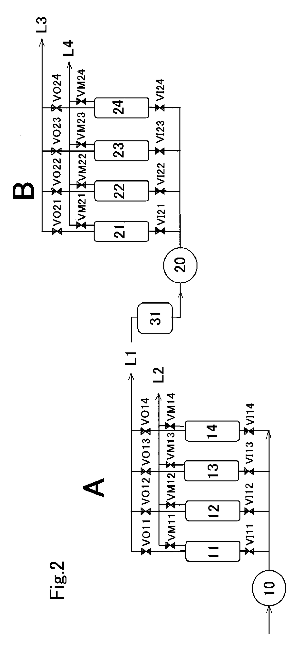
[0091]A gas purification test was carried out, in which hydrogen gas was recovered using the post-pyrolysis reformed gas produced in the same manner as in Example 1. As a hydrogen recovery apparatus, the same apparatus as that in Example 1 was used, except that about 150 g of Zeolite A-5 (manufactured by Wako Pure Chemical Industries, Ltd.) as an adsorbent was charged into each of four adsorption columns (21, 22, 23, 24) in the second purification step (B). The purification conditions were also the same as in Example 1, except that the first purified gas (L1) was charged so that the internal pressures of the first adsorption column (21) to the fourth adsorption column (24) were 0.5 MPa in the second purification step (B).

[0092]The results of analyzing the purified gas (second purified gas (L3)) in the second purification step (B) using gas chromatography [GC-14A (trademark) manufactured by Shimadzu Corporation, carrier gas: argon] are as shown in the following Table 8, and the hydro...


PUM

PropertyMeasurementUnit
pressureaaaaaaaaaa
pressureaaaaaaaaaa
pressureaaaaaaaaaa

Abstract

Provided is a hydrogen recovery method such that highly concentrated hydrogen gas can be obtained efficiently by adsorbing and removing hydrocarbon gas such as carbon dioxide, carbon monoxide, and methane, using a relatively low pressure, from pyrolysis gas obtained by heat treating biomass. The present invention is the method for recovering hydrogen from pyrolysis gas obtained by heat treating biomass, characterized by including: a first purifying step of adsorbing and removing gas that mainly includes carbon dioxide under pressure from the pyrolysis gas to purify the pyrolysis gas; and a second purifying step of further adsorbing and removing gas that includes carbon dioxide under pressure from purified gas obtained by the first purifying step at a pressure lower than the pressure in the first purifying step to purify the purified gas in order to recover hydrogen from the purified gas.

Description

TECHNICAL FIELD[0001]The present invention relates to a hydrogen recovery method, and more specifically relates to a method for recovering hydrogen from pyrolysis gas obtained by heat-treating biomass. In the present invention, the term “pyrolysis gas” includes the above-described pyrolysis gas obtained by heat-treating biomass, gas obtained by further steam-reforming the pyrolysis gas, and the like.BACKGROUND ART[0002]In recent years, household cogeneration apparatuses and fuel-cell vehicles using solid polymer-type fuel cells have been practicalized and commercialized. Accordingly, research and development of techniques for producing, storing and transporting hydrogen have been activated.[0003]Conventionally known methods for producing hydrogen include, e.g.; a method for separating and recovering hydrogen from coke oven gas; a method for separating and recovering hydrogen from blast furnace gas; a method for separating and recovering hydrogen from naphtha-reformed gas generated i...

Claims


Application Information

Patent Timeline
Patent Type & Authority Applications(United States)
IPC IPC(8): B01D53/047C01B3/56C10K1/32C10K3/04
CPCB01D53/047C01B3/56C10K1/32C10K3/04B01D2256/16B01D2256/20B01D2256/22B01D2257/504B01D53/002C01B2203/043C01B2203/0475Y02C20/40Y02P20/151Y02P20/129C01B2203/146C01B2203/0233B01D2259/402B01D2259/404
Inventor DOWAKI, NAOKIKAMEYAMA, MITSUODOWAKI, KIYOSHI
Owner JBEC CO LTD
Learn More