
System and method for power control of an over-the-air RF environment emulator

a radio frequency environment emulator and system control technology, applied in power management, transmission monitoring, receiving monitoring, etc., can solve problems such as system noise problems, platform noise-limited cases suffer from system level noise, and system noise problems, so as to reduce internal gain and prevent damage

Active Publication Date: 2018-11-01
ETS-LINDGREN
View PDF2 Cites 6 Cited by
  • Summary
  • Abstract
  • Description
  • Claims
  • Application Information

AI Technical Summary

Benefits of technology

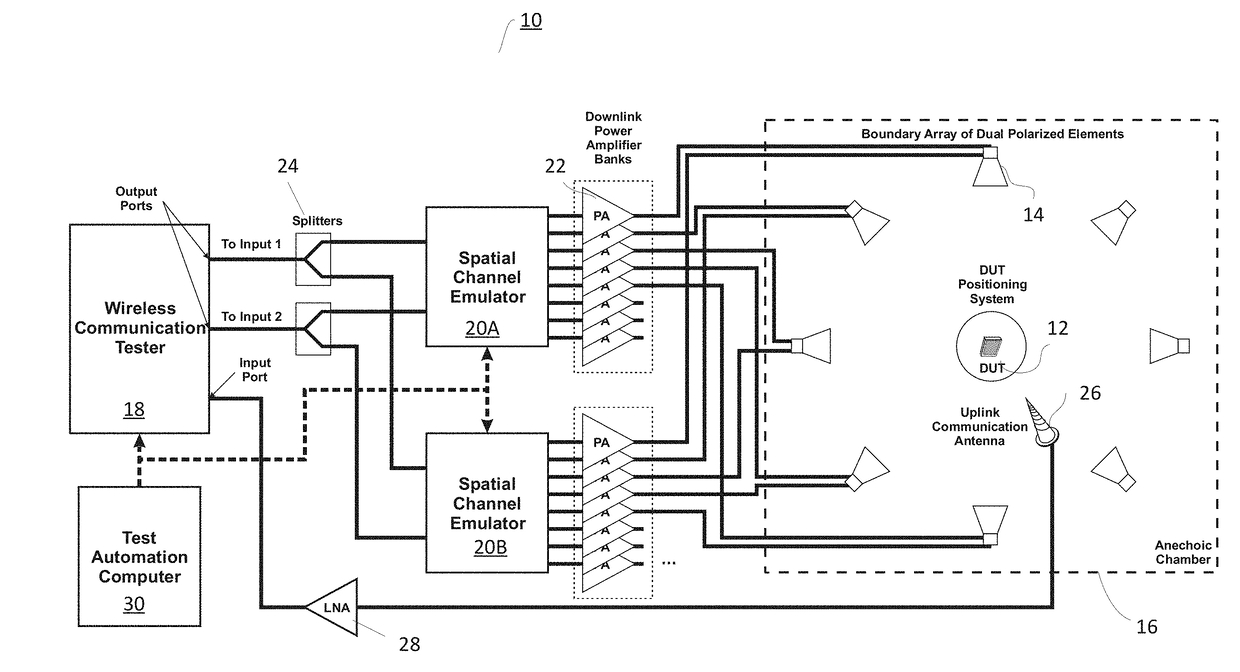
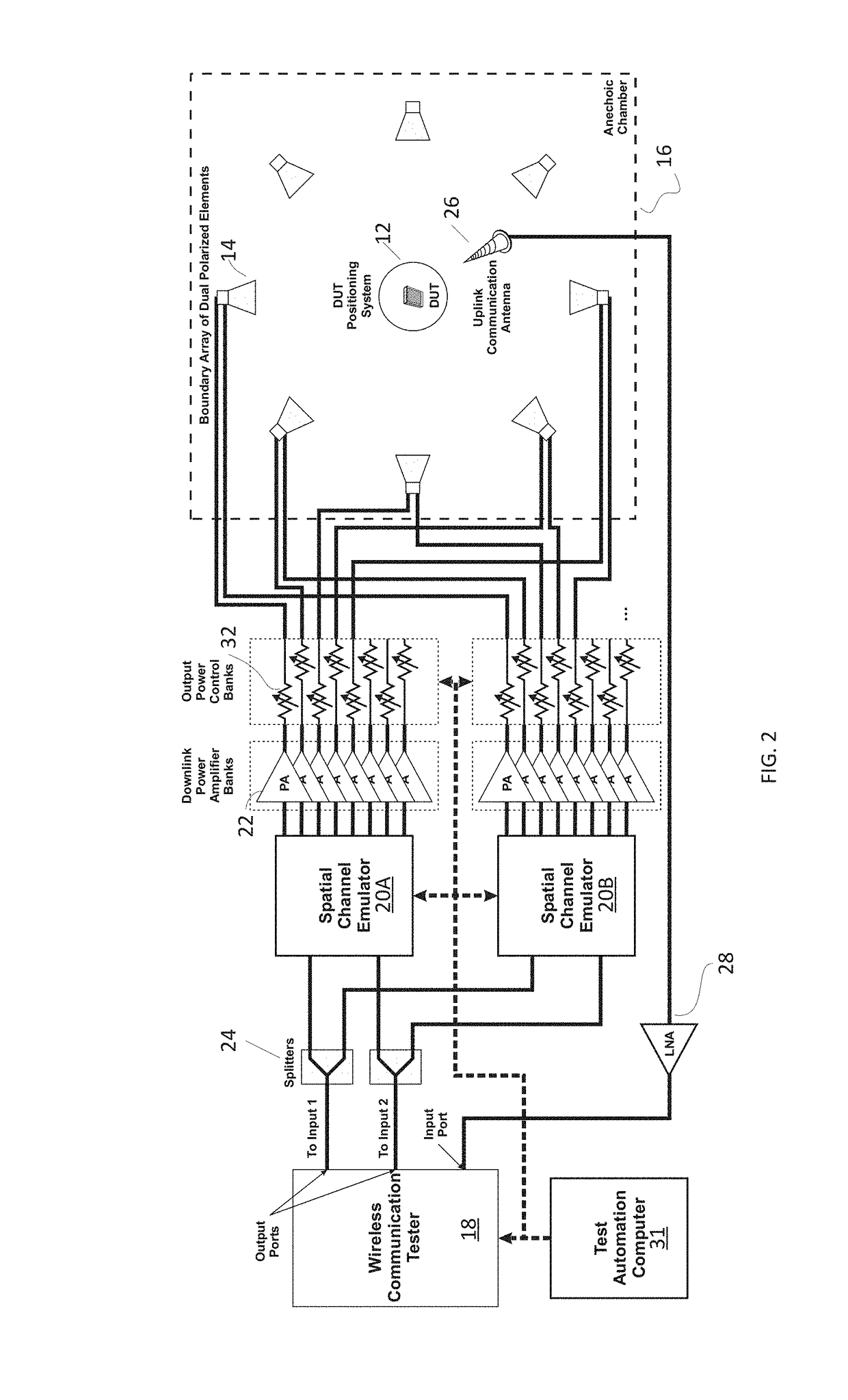
The patent introduces a new test system that uses a dynamic power control function to overcome limitations of existing methods. This function reduces the internal gain of each amplifier in the system while adding attenuation after each amplifier to control the output power. The system keeps the output signal of the channel emulator near its maximum SNR. The dynamic power control function can control the entire desired range of power levels for the test, but in practical cases, it is difficult to control the output power of each amplifier separately. Therefore, a hybrid power control is desired where both the output gain / attenuation is controlled and the signal level of the channel emulator is varied over a narrow range of operation at a high SNR. The software and / or embedded firmware algorithm combines the various power control features into one seamless linear power control range and prevents damage from switching conditions during the normal operation of the system.

Problems solved by technology

This is not always possible because amplifiers cannot be made perfectly flat, and because different models of channel emulators from different manufacturers have different maximum output levels.
Unfortunately, when trying to build a system to meet the requirements of the SIR based test, the platform noise-limited case suffers from system level noise introduced by the test system itself.
While a real amplifier introduces some of its own noise into the test system as well, this system noise problem would exist even if a perfect amplifier (a perfect gain source with no inherent noise figure) could be used.
Unfortunately, even if the SIR usage case is ignored and one only attempts to choose a gain suitable to overcome the system path loss for the platform noise limited test case, there is no simple solution.
Tuning a broadband amplifier to compensate for all of these factors and provide a constant net gain to the center of the test volume could be nearly impossible.
In some cases, the output power control of the amplifier output would be sufficient to control the entire desired range of power levels used for the test, but various factors of currently available components make that unlikely.

Method used


Image

  • System and method for power control of an over-the-air RF environment emulator
  • System and method for power control of an over-the-air RF environment emulator
  • System and method for power control of an over-the-air RF environment emulator

Examples


Embodiment Construction

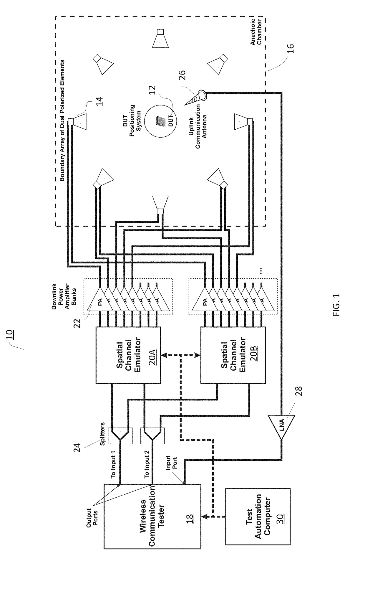
[0032]Before describing in detail exemplary embodiments, it is noted that the embodiments reside primarily in combinations of apparatus components and processing steps related to an improved system and method for power control of an electromagnetic test system such as an over-the-air radio frequency (RF) environment emulator or electromagnetic test system. Accordingly, components have been represented where appropriate by conventional symbols in the drawings, showing only those specific details that are pertinent to understanding the embodiments so as not to obscure the disclosure with details that will be readily apparent to those of ordinary skill in the art having the benefit of the description herein.

[0033]As used herein, relational terms, such as “first” and “second,”“top” and “bottom,” and the like, may be used solely to distinguish one entity or element from another entity or element without necessarily requiring or implying any physical or logical relationship or order betwe...


PUM


Abstract

Methods, tests systems and computers for controlling power delivered to a test volume are provided. According to one aspect, an electromagnetic test system has at least one operational path having a channel emulator output, an amplifier, an attenuator and an antenna. A method includes, for a given desired output power level, C, setting a channel emulator output power to a power level B, and setting the attenuator to a setting A, such that C is a function of B and A. In such embodiments, the attenuation A is calculated based on an upper limit output power of the channel emulator and the desired output power C.

Description

FIELD[0001]This disclosure relates to electromagnetic measurement systems, and in particular to an improved system and method for power control of an over-the-air radio frequency (RF) environment emulator.INTRODUCTION[0002]U.S. Pat. No. 8,331,869 B2 describes systems and methods for over-the-air performance testing of wireless devices with multiple antennas. This class of system, referred to as a boundary array system, reproduces a radiated near-field environment that appears to the device in the test volume as though it originated in the far field and had the multipath characteristics of a chosen emulated environment. The device under test (DUT) within the test volume is typically isolated from the real world by an RF absorber lined anechoic chamber to produce a free-space environment, and then an array of antennas is used to reproduce the RF boundary condition and provide the directional characteristics around the DUT inherent in the chosen spatial channel model to be emulated.[00...

Claims


Application Information

Patent Timeline
IPC IPC(8): H04W52/04H04B17/29
CPCH04W52/04H04B17/29H04B17/3911H04B17/3912H04B17/13
Inventor FOEGELLE, MICHAEL DAVID
Owner ETS-LINDGREN
Learn More