
Separator having electrode adhesive layer and electrochemical device including the same

a technology of electrode adhesive layer and electrode, which is applied in the direction of electrochemical generator, cell component details, cell components, etc., can solve the problems of reducing the air permeability of the separator and/or increasing the electrical resistance of the battery, and achieves excellent bindability, prevents or minimizes the infiltration phenomenon into the pores or voids, and high adhesion to the electrode

Active Publication Date: 2018-11-01
LG ENERGY SOLUTION LTD
View PDF4 Cites 12 Cited by
  • Summary
  • Abstract
  • Description
  • Claims
  • Application Information

AI Technical Summary

Benefits of technology

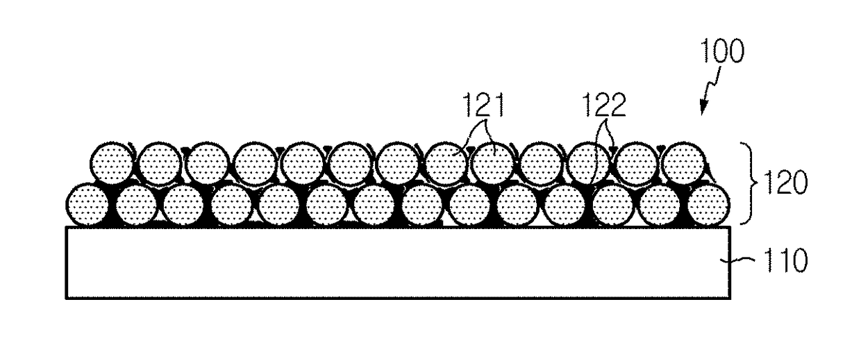
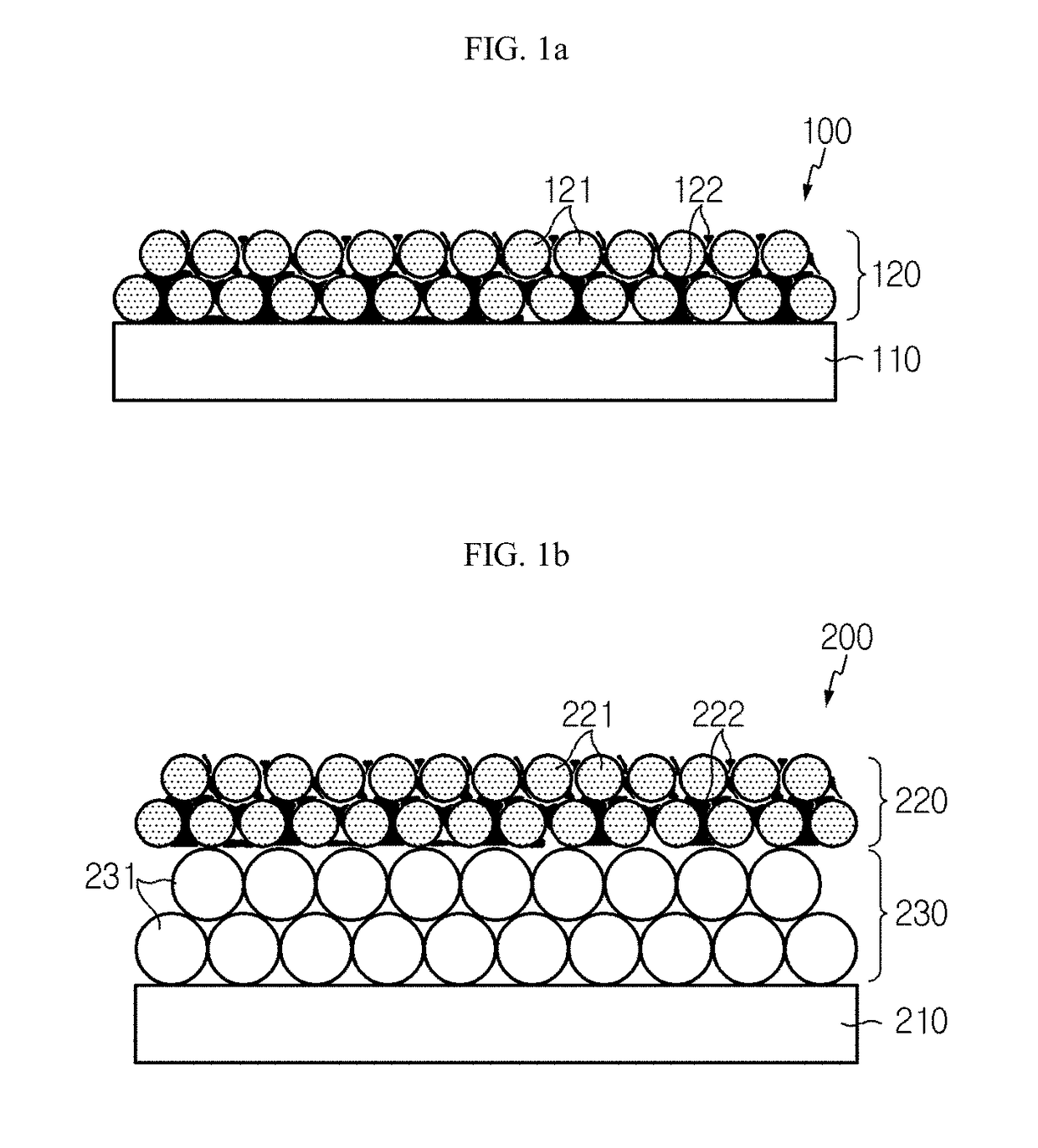
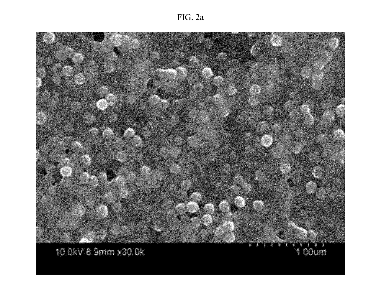
The present patent text describes a separator used in an electrode adhesive layer. The separator prevents particles from entering the underlying constitutional element's pores or voids, even if the particles have a smaller diameter than the pores. The separator also adheres very well to the electrode, providing strong binding. The electrode adhesive layer uses an acrylic resin binder to anchor the organic particles to the underlying constitutional element, while the voids among the particles improve air permeability. This results in improved safety and performance of the electrochemical device.

Problems solved by technology

However, the separator has a problem in that the electrode adhesive layer blocks the pores formed on the surface of the separator and / or the particles forming the electrode adhesive layer infiltrate into the pores, thereby significantly reducing the air permeability of the separator and / or increasing the electrical resistance of a battery.

Method used


Image

  • Separator having electrode adhesive layer and electrochemical device including the same
  • Separator having electrode adhesive layer and electrochemical device including the same
  • Separator having electrode adhesive layer and electrochemical device including the same

Examples


example 1

[0095]First, a polyethylene porous film (Asahi, ND307B) having a thickness of 7 μm was prepared as a porous polymer substrate.

[0096]Next, 7000 g of inorganic particles (Al2O3, Nippon Light Metal, LS235, 500 nm) and 105 g of carboxymethyl cellulose (CMC) were introduced to water as a solvent and then crushed and pulverized by using a ball milling process for 3 hours to obtain slurry. The slurry included inorganic particles dispersed homogeneously therein and 700 g of a binder (acrylic resin, TRD202A) was introduced thereto before coating, and then the slurry was agitated for 1 hour. The slurry was coated onto both surfaces of polyethylene to a thickness of 3 μm through a dip coating process and then dried at 80° C.

[0097]Then, 1800 g of organic particles (PVdF-HFP, Solvay, XPH883, Tm 100° C., average particle diameter 300 nm, solid content 25%) and 1125 g of an acrylic resin binder (acrylic resin, JSR, TRD202A, Tg−5° C., solid content 40%) were introduced to water as a solvent to obta...

example 2

[0098]A separator having an electrode adhesive layer was obtained in the same manner as Example 1, except that 2520 g of organic particles (PVdF-HFP, Solvay, XPH883, Tm 100° C., average particle diameter 300 nm, solid content 25%) and 675 g of an acrylic resin binder (acrylic resin, JSR, TRD202A, Tg−5° C., solid content 40%) were used (30 wt % of the acrylic resin binder based on the combined weight of the organic particles and the acrylic resin binder).

example 3

[0099]A separator was obtained in the same manner as Example 1, except that 40 wt % of the acrylic resin binder was used based on the combined weight of the organic particles and the acrylic resin binder.


PUM

PropertyMeasurementUnit
glass transition temperatureaaaaaaaaaa
dielectric constantaaaaaaaaaa
surface roughness Raaaaaaaaaaa

Abstract

Disclosed are a separator having an electrode adhesive layer and an electrochemical device including the same. The electrode adhesive layer includes organic particles and an acrylic resin binder. Preferably, the acrylic resin binder is present in an amount of 30 wt % or more, so that a film-shaped electrode adhesive layer can be formed even when the organic particles have a particle diameter smaller than that of the pores of the underlying substrate or voids of the underlying porous coating layer.

Description

TECHNICAL FIELD[0001]The present application claims priority to Korean Patent Application No. 10-2015-0158312 filed on Nov. 11, 2015 and Korean Patent Application No. 10-2015-0158322 filed on Nov. 11, 2015 in the Republic of Korea, the disclosures of which are incorporated herein by reference.[0002]The present disclosure relates to a separator having an electrode adhesive layer and an electrochemical device including the same.BACKGROUND ART[0003]Recently, energy storage technology has been given increasing attentions. Efforts into research and development for electrochemical devices have been actualized more and more, as the application of energy storage technology has been extended to energy for cellular phones, camcorders and notebook PC and even to energy for electric vehicles. In this context, electrochemical devices have been most spotlighted. Among such electrochemical devices, development of rechargeable secondary batteries has been focused.[0004]Continuous studies have devel...

Claims


Application Information

Patent Timeline
Patent Type & Authority Applications(United States)
IPC IPC(8): H01M2/16H01M10/0525H01M50/417H01M50/42H01M50/426H01M50/429H01M50/443H01M50/451H01M50/457
CPCH01M2/1686H01M2/1653H01M2/166H01M10/0525Y02E60/10H01M50/417H01M50/429H01M50/457H01M50/451H01M50/443H01M50/426H01M50/42H01M10/052H01M50/446H01M50/461H01M50/449H01M50/414H01M50/431H01M50/491H01M50/489Y02T10/70
Inventor KWON, HYE-JINJEONG, SO-MIKIM, JI-EUNLEE, JOO-SUNGJIN, SUN-MI
Owner LG ENERGY SOLUTION LTD
Learn More