Method for producing pouch battery

a technology of a pouch battery and a battery body is applied in the field of producing a pouch battery, which can solve the problems of adverse effects on the battery performance and especially on the long-term cycle characteristic, and achieve the effects of reducing the formation of creases, excellent battery performance and reducing creases

Active Publication Date: 2018-10-25
TOYOTA JIDOSHA KK
View PDF8 Cites 4 Cited by
  • Summary
  • Abstract
  • Description
  • Claims
  • Application Information

AI Technical Summary

Benefits of technology

[0027]According to the disclosure it is possible to provide a method for producing a pouch battery that can reduce formation of creases on the main sides and the lateral sides of the laminate film exterior body. The pouch battery produced by the method of the disclosure has reduced creases on the main sides of the laminate film exterior body, allowing constraining pressure to be evenly applied to the cell stack when the pouch battery has been constrained, and therefore the battery performance is excellent. In addition, since creases in the lateral sides of the laminate film exterior body are also reduced and there is no interference when the sealed sections are folded, it is possible to minimize the volume of the sizes of the portions that do not contribute to cell function, thereby allowing the output per volume to be maximized.

Problems solved by technology

In a pouch battery, creases generated at portions of the laminate film exterior body that cover the main sides of the cell stack result in uneven constraining pressure being applied to the cell stack when the pouch battery is constrained, producing an adverse effect on the battery performance and especially on the long-term cycle characteristic.

Method used


Image

  • Method for producing pouch battery
  • Method for producing pouch battery
  • Method for producing pouch battery

Examples


Embodiment Construction

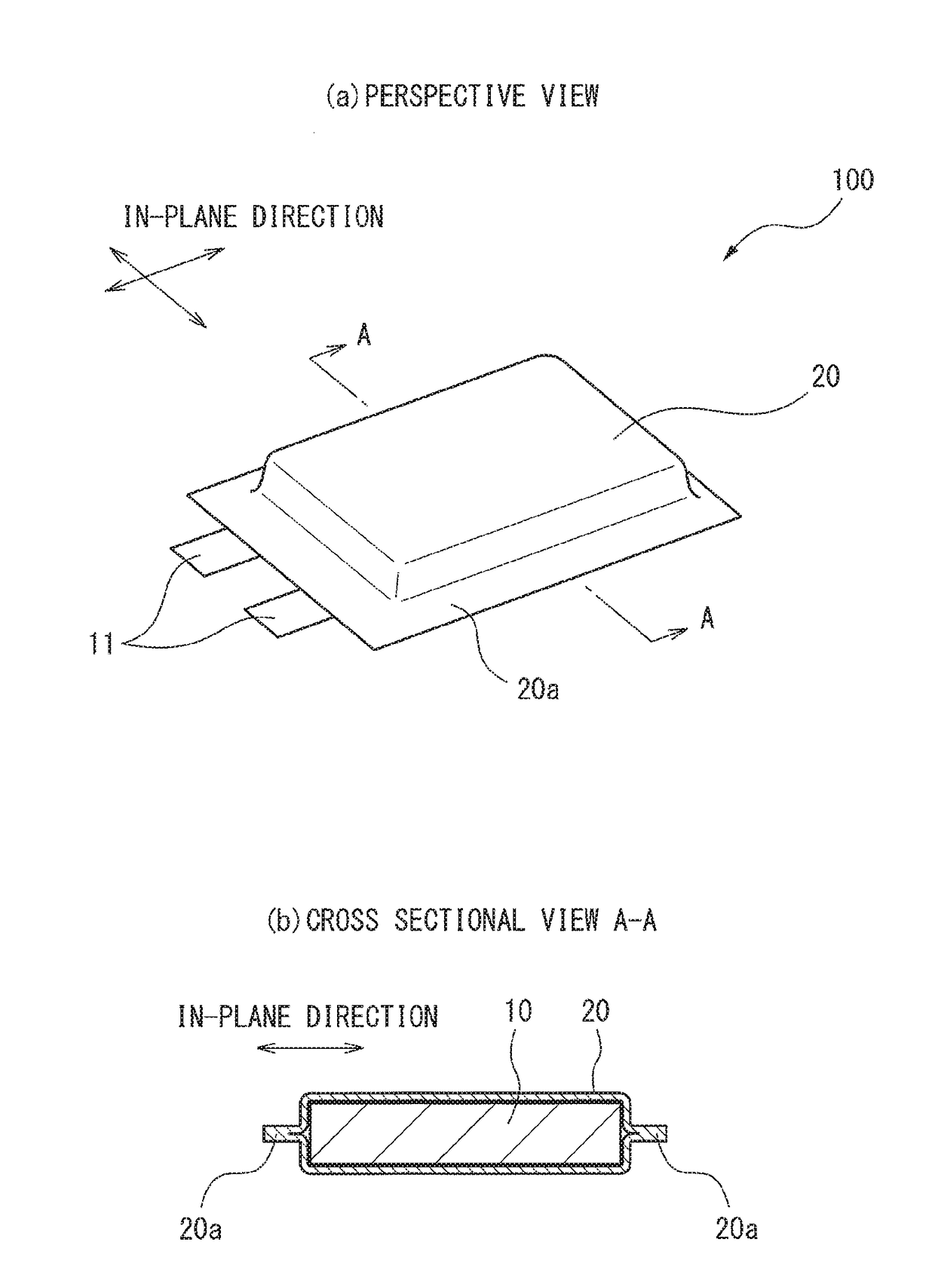
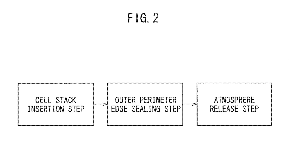
[0037]The method for producing a pouch battery of the disclosure is a method comprising:

[0038]inserting a cell stack in a laminate film exterior body,

[0039]sealing the outer perimeter edges of the laminate film exterior body in which the cell stack has been inserted, in an airtight chamber in a state of reduced pressure,

[0040]applying tensile force outward in the in-plane direction at two facing locations in the in-plane direction on the outer perimeter edges of the laminate film exterior body, and

[0041]raising the pressure in the airtight chamber to atmospheric pressure while maintaining the application of tensile force outward in the in-plane direction of the laminate film exterior body.

[0042]Throughout the present specification, the term “in-plane direction” refers to the direction in the plane perpendicular to the direction of stacking of the cell stack. Of the sides of the cell stack, the two sides that are perpendicular to the direction of stacking of the cell stack and situat...


PUM

PropertyMeasurementUnit
pressureaaaaaaaaaa
tensile forceaaaaaaaaaa
atmospheric pressureaaaaaaaaaa

Abstract

[PURPOSE]To provide a method for producing a pouch battery that can reduce formation of creases on the main sides and the lateral sides of the laminate film exterior body.[SOLUTION MEANS]A method for producing a pouch battery that comprises a cell stack insertion step in which a cell stack is inserted in a laminate film exterior body, an outer perimeter edge sealing step in which the outer perimeter edges of the laminate film exterior body in which the cell stack has been inserted are sealed in an airtight chamber in a state of reduced pressure, a tensile force applying step in which tensile force is applied to the outer sides in the in-plane direction at two facing locations in the in-plane direction on the outer perimeter edges of the laminate film exterior body, and a tensile force-maintained air release step, in which application of tensile force to the outer sides of the laminate film exterior body in the in-plane direction is maintained while the pressure in the airtight chamber is raised to atmospheric pressure.

Description

TECHNICAL FIELD[0001]The present disclosure relates to a method for producing a pouch battery.BACKGROUND ART[0002]Pouch batteries are known that have a cell stack encapsulated in a laminate film exterior body.[0003]In a pouch battery, creases generated at portions of the laminate film exterior body that cover the main sides of the cell stack result in uneven constraining pressure being applied to the cell stack when the pouch battery is constrained, producing an adverse effect on the battery performance and especially on the long-term cycle characteristic. Therefore, techniques for minimizing formation of creases in laminated exterior bodies have been proposed.[0004]For example, PTL 1 describes a method for producing a pouch battery comprising:[0005]a forming step in which a laminate film is formed into a cup section that can receive a flat-shaped cell stack,[0006]a housing step in which the flat-shaped cell stack is housed into the formed laminate that has been formed in the formin...

Claims


Application Information

Patent Timeline
Patent Type & Authority Applications(United States)
IPC IPC(8): H01M2/02H01M10/04H01M50/105H01M50/126
CPCH01M2/021H01M10/0436H01M10/0404Y02E60/10Y02P70/50H01M50/126H01M50/105
Inventor FUJISHIMA, SEIGO
Owner TOYOTA JIDOSHA KK
Why Eureka
Try Eureka