Method for the additive production of relief printing plates

a technology of relief printing plate and additive production, which is applied in the direction of microlithography exposure apparatus, photomechanical treatment, instruments, etc., can solve the problems of complex process, unirradiated regions of flexographic printing plate becoming tacky, and crosslinked regions of flexographic printing plate also undergoing swelling

Active Publication Date: 2018-10-25
FLINT GROUP GERMANY GMBH
View PDF5 Cites 0 Cited by
  • Summary
  • Abstract
  • Description
  • Claims
  • Application Information

AI Technical Summary

Problems solved by technology

When the relief is subjected to leaching, the crosslinked regions of the flexographic printing plate also undergo some degree of swelling.
The unirradiated regions of the flexographic printing plate thus become tacky and are then removed via contact with a nonwoven fabric or a woven fabric.
However, the process involves complicated apparatus, because successive removal of a plurality of layers is required in order to produce an adequate relief.
The resolution of the resultant flexographic printing plates is moreover inferior to the resolution of solvent-leached flexographic printing plates.
However, build-up of a flexographic printing plate by means of an inkjet printing process has important disadvantages.
These monomers are not capable of forming a soft resilient, robust material of the type required for flexographic printing plates.
Since the reactive monomers are mostly selected from acrylic or methacrylic esters, the resultant materials are either too hard or, although sufficiently soft, not resistant to the polar inks used in flexographic printing.
However, this process in turn requires removal of the carrier liquid, and is therefore complicated.
The process requires complicated apparatus.
However, the protective film should be permeable to the monomer, since otherwise no diffusion is possible, and no build-up of relief is possible.

Method used


Image

  • Method for the additive production of relief printing plates
  • Method for the additive production of relief printing plates
  • Method for the additive production of relief printing plates

Examples


experiment 1

[0104

[0105]Holes measuring 1 mm, 3 mm and 10 mm were punched into an aluminum sheet of thickness about 0.5 mm to produce a template. This template was placed onto the SIS-based carrier layer (table 1) and loaded with weights at the edges in order to ensure intimate contact between mask and surface of the polymeric carrier layer.

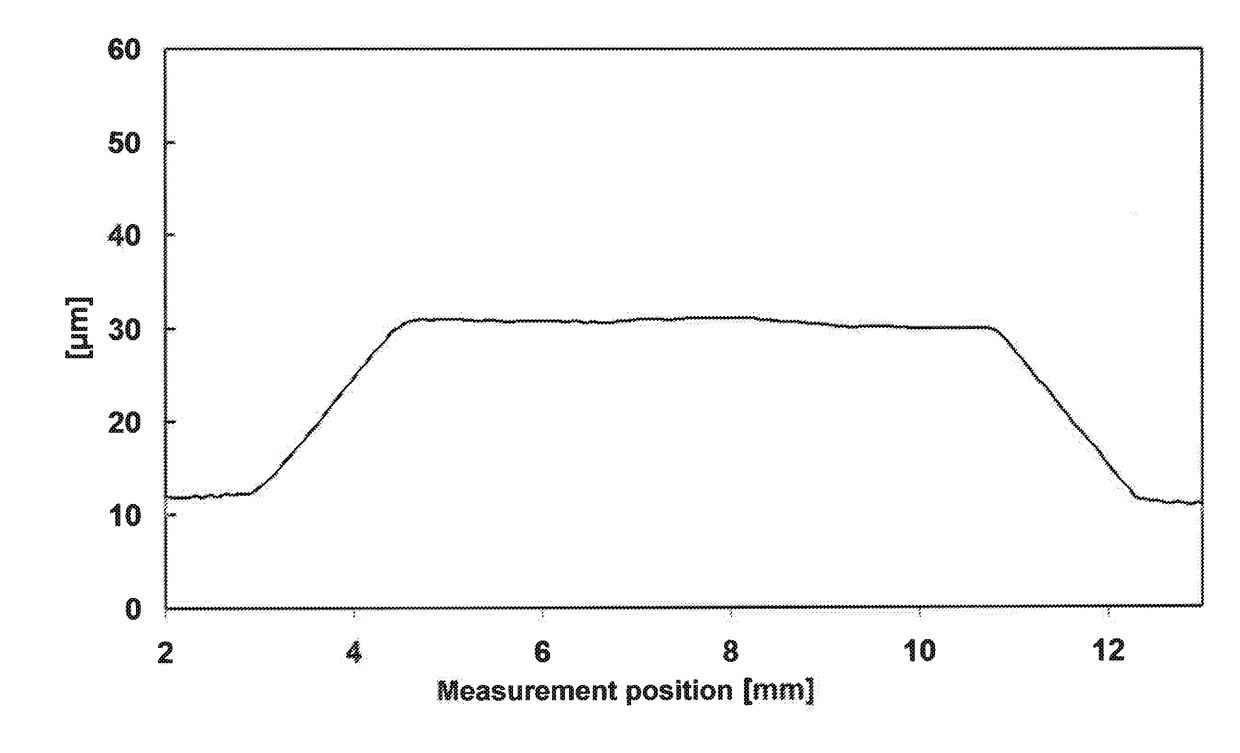
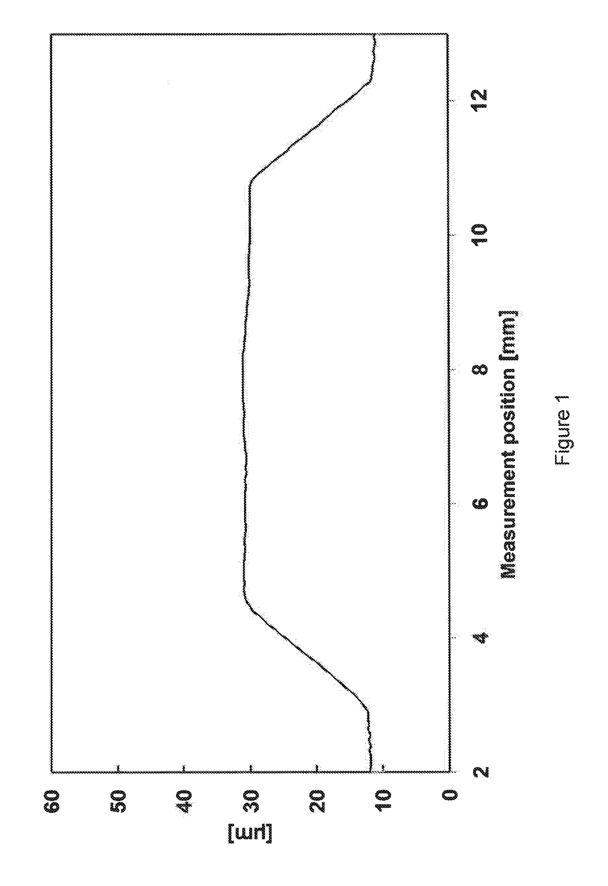
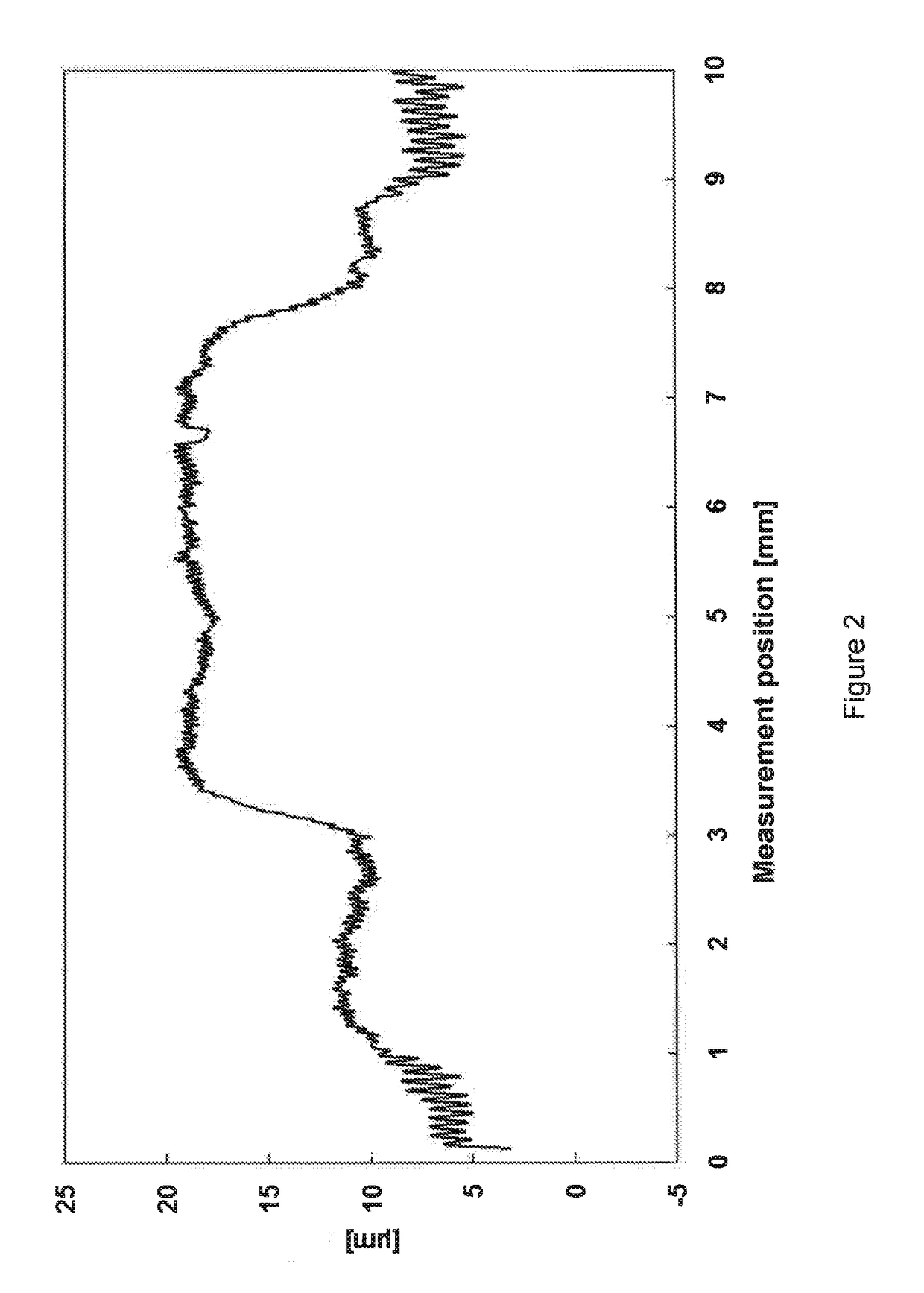
[0106]The holes in the template were filled with HDA2 at room temperature (22° C.). After a diffusion time of 60 minutes, the template was removed from the carrier layer. Excess monomer was removed by washing with isopropanol, and the relief plate was blow-dried with compressed air. The relief was then fixed by irradiation with UVA light (10 minutes, nyloflex F III lamp), and the surface was detackified by means of UVC irradiation (3 minutes, nyloflex F III lamp). A Perthometer was used to measure the resultant relief (see FIGS. 4, 5 and 6).

[0107]The built-up spots had steep sides. The spot surfaces were level and uniform. The relief heights determined were 4...

experiment 2

[0108

[0109]Experiment 1 was repeated, except that the temperature for diffusion of the monomer into the material was set to 40° C.

[0110]Again, the built-up spots had steep sides and a level, uniform surface. Relief height was greater because of the higher diffusion velocity. The relief heights were 108 μm (10 mm spot), 106 μm (3 mm spot) and 108 μm (1 mm spot).

[0111]A compressible adhesive tape was then used to bond the relief printing plate to the cylinder of a flexographic printing machine, and alcohol-based ink was used for printing. Table 3 collates the printing parameters.

TABLE 3Printing machineF&K FP 6S / 8SubstratePE sheetPrinting inkSiegwerk NC4012 cyanViscosity of printing ink22 secAnilox roll460 l / cm, 3.5 g / cm3Adhesive tapeLohmann 5.3Print velocity80 m / minPrint setting+30 μm in relation to kiss print

[0112]Printout of all of the relief spots was uniform with the print setting selected. Each printed spot exhibited full coverage and no excessive squeeze edge. The diameters of t...


PUM

PropertyMeasurementUnit
diffusion velocityaaaaaaaaaa
temperatureaaaaaaaaaa
relief depthaaaaaaaaaa

Abstract

The invention relates to a process for the production of relief printing plates, where a carrier with a polymeric substrate layer is provided and a relief is formed layer-by-layer on a surface of the substrate layer, where the relief is formed by means ofa) single or multiple application of a liquid comprising at least one reactive monomer to the surface of the substrate layer,b) diffusion of the reactive monomer into the polymeric substrate layer for a prescribed exposure time andc) hardening of the relief,where in step a) the liquid is applied in accordance with an image to the surface and where, after the prescribed exposure time of step b), any liquid that remains on the surface, having not diffused into the material, is removed from the surface, and in step c) the relief that is hardened comprises the polymer of the substrate layer and reactive monomer that has diffused into the material.

Description

PRIOR ART[0001]The invention relates to a process for the production of relief printing plates where a carrier with a polymeric substrate layer is provided and a relief is formed layer-by-layer on a surface of the substrate layer.[0002]Relief printing plates, for example flexographic printing plates, are used by way of example for the printing of a very wide variety of packaging with low-viscosity printing inks. Printing inks used are mostly polar water- or alcohol-based printing inks. The printing process requires flexographic printing plates that are soft and resilient, and are resistant to polar flexographic printing inks.[0003]Conventional flexographic printing plates therefore comprise a soft, resilient, nonpolar binder, mostly block copolymers based on styrene-isoprene or styrene-butadiene, in combination with monomers, plasticizers and one or more photoinitiators (see by way of example U.S. Pat. No. 4,323,636). This photopolymerizable layer generally has a thickness of a few ...

Claims


Application Information

Patent Timeline
Patent Type & Authority Applications(United States)
IPC IPC(8): B41C1/00G03F7/00G03F7/027G03F7/20
CPCB41C1/003G03F7/0035G03F7/027G03F7/2022
Inventor TELSER, THOMASFREUDENTHALER, EVA
Owner FLINT GROUP GERMANY GMBH
Why Eureka
Try Eureka