
Coulomb friction damped components and method for manufacturing same

a technology of friction damped components and friction, which is applied in the direction of rotors, braking discs, stators, etc., can solve the problems of vibration in the vehicle, other parts, such as suspension parts, are subject to vibration during vehicle movement, and other problems, to achieve the effect of reducing the squeal and increasing the damping capacity of the disc brake rotor

Active Publication Date: 2018-10-18
FORD GLOBAL TECH LLC
View PDF3 Cites 0 Cited by
  • Summary
  • Abstract
  • Description
  • Claims
  • Application Information

AI Technical Summary

Benefits of technology

The invention is a new way to make brakes for vehicles that reduces the noise and vibration when braking. It does this by adding a special two-part insert with a metal sheath and thin core during the casting process of the brakes. This insert helps to damp out the vibrations and resonances that can cause noise when braking. The brakes also have small openings in the sheath to allow limited infiltration of cast iron material and prevent distortion during assembly. Overall, this new method makes brakes that are quieter, more stable, and have better contact pressure between the brakes and the vehicle's suspension system.

Problems solved by technology

Some of these components, such as the brake rotor, are subject to vibration during braking.
Others, such as suspension parts, are subject to vibration during vehicle movement.
Still others, such as the vehicle engine block, are subject to vibration at any time the vehicle engine is on.
The disc brake system is particularly subject to vibration and the resulting undesirable noise, vibration and harshness.
Under light pressures often used by customers to control vehicle speed, brake pads can make only a partial contact with rotor surfaces leading to unstable friction between the brake pads and the rotor.
Unstable behavior of the disc / pad friction pair can cause a resonant vibration in the brake disc.
Since grey cast iron material typically used for brake discs has relatively low damping capacity, the disc resonant vibration amplitude might built up to produce objectionable squeal noise.
This noise is a significant, recurring, and stubborn source of customer complaints to vehicle manufacturers.
Unfortunately, none of the friction damper proposals using embedded solid inserts have yet been implemented for mass production because of concerns related to the structural integrity of the modified brake rotors.
The primary challenge of these proposals includes the need for the insert surfaces to have both an ability of sliding inside the disc plate for friction damping and a proper bonding to the base rotor material to ensure the structural integrity of the rotor.
In reality, it is very difficult to always satisfy such contradictory requirements for the same friction interface.
However, such pre-treatment can lead to insufficient bonding between the insert and rotor surfaces, which may impact brake rotor structural integrity, representing a safety concern.
Other cast components, such as suspension components and the engine block as mentioned above, are subject to vibration during operation.
Many of the same problems attributed to the disc rotor arise in these components during vehicle operation.
However, despite these improvements in the state of the art, there yet remains room in the technology of cast vehicle components for improvements that yield a reduction in noise, vibration and harshness without compromising structural integrity.

Method used


Image

  • Coulomb friction damped components and method for manufacturing same
  • Coulomb friction damped components and method for manufacturing same
  • Coulomb friction damped components and method for manufacturing same

Examples


Embodiment Construction

[0034]In the following figures, the same reference numerals will be used to refer to the same components. In the following description, various operating parameters and components are described for different constructed embodiments. These specific parameters and components are included as examples and are not meant to be limiting.

[0035]Friction damping has a preferred range of contact force (contact pressure) within which it becomes most effective. Below such an optimum range, excess relative motion at the interface develops without significant energy dissipation. Above it, excess contact pressure limits the development of relative motion for friction to act as an effective damper.

[0036]Contact pressure between two surfaces depends on their contact geometry and elastic properties which are known to change with surface temperature and temperature gradients. The operating temperature range for brake rotors is very wide, ranging from approximately −40° C. (after overnight soaks outside...


PUM

PropertyMeasurementUnit
temperatureaaaaaaaaaa
coulomb frictionaaaaaaaaaa
areaaaaaaaaaaa

Abstract

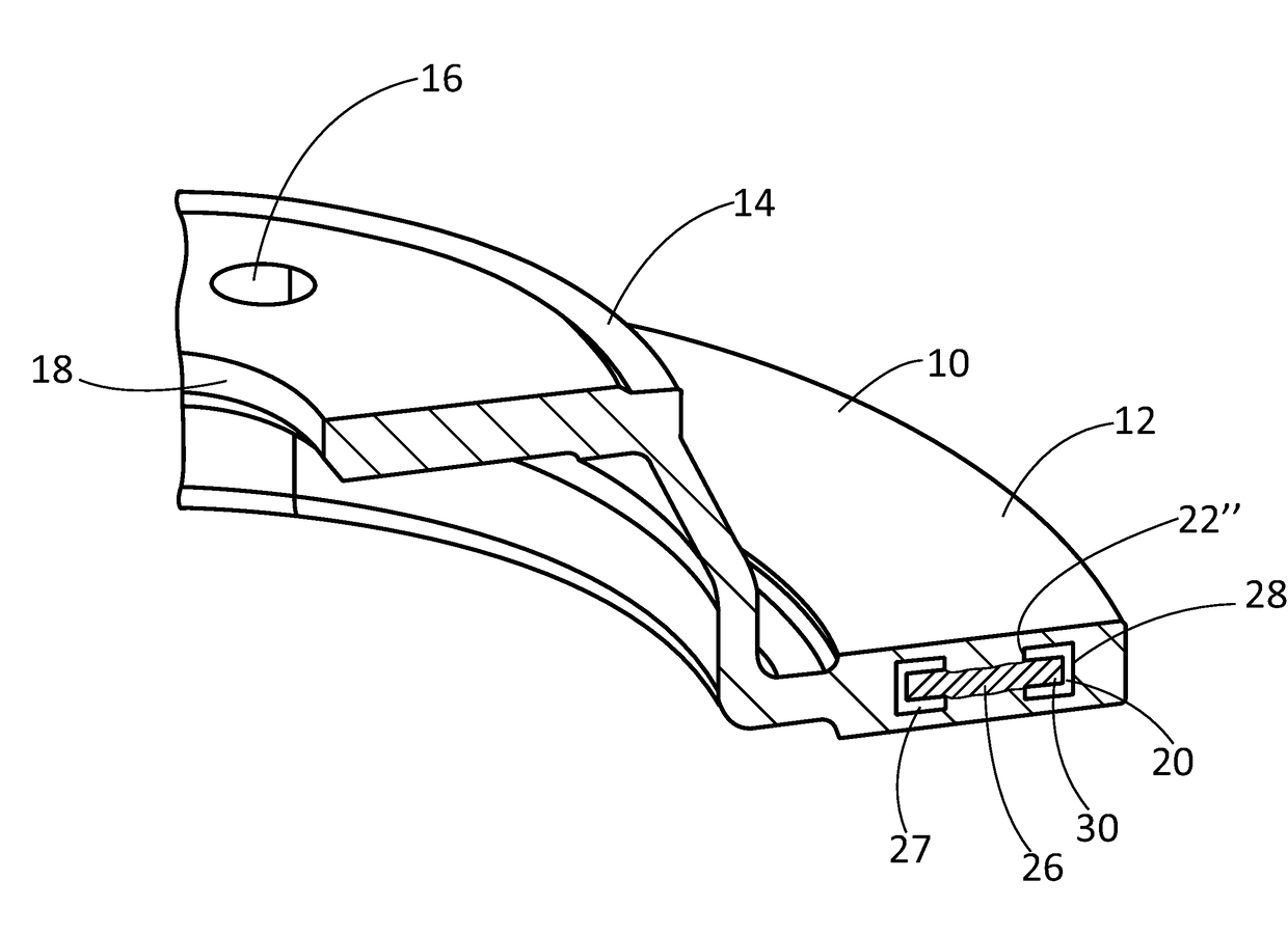
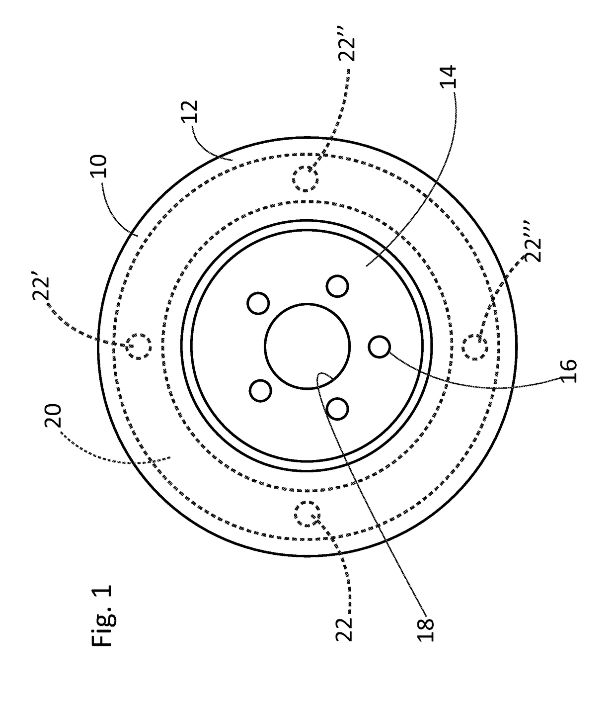
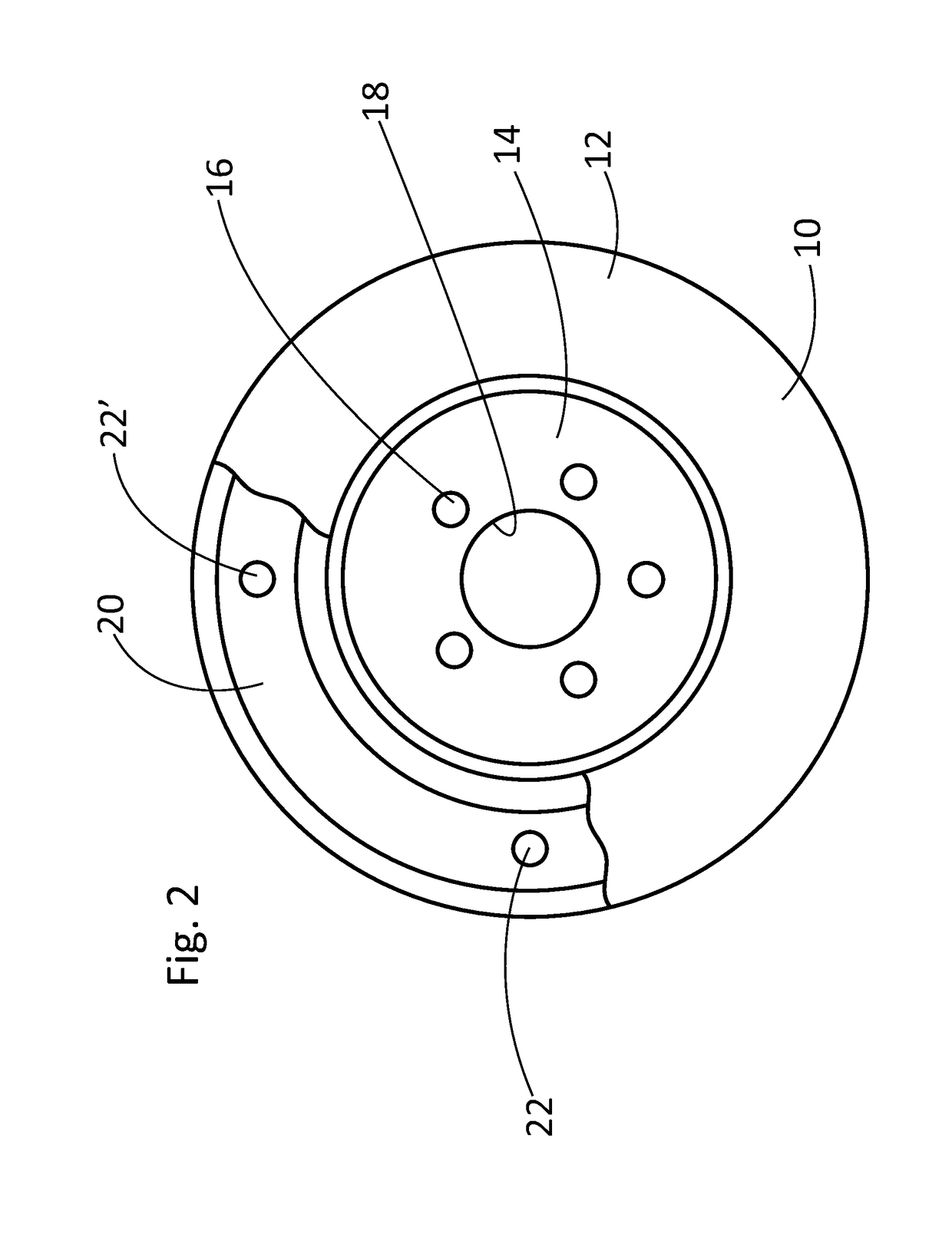
A friction damping cast component and method of production are disclosed. The components may be rotary, such as a cast brake rotor, or may be non-rotary, such as a cast suspension part or a cast engine block. Regardless of the type of component, a two-part vibration-damping insert having a thin metal core and a thin metal sheath is provided. The sheath fully encompasses the core in such a way that a dry sliding friction contact develops at their interfaces. The outer surface of the sheath with the metal core inside is rigidly bonded to the cast material that surrounds it during the casting process. The sheath surfaces may have a number of openings that allow a limited infiltration of molten cast iron material just inside the immediate vicinity of the sheath openings for spot rigid bonding between the surrounding cast material and the insert surfaces during casting.

Description

TECHNICAL FIELD[0001]The disclosed inventive concept relates to friction damped components for a vehicle. More particularly, the disclosed inventive concept relates to a coulomb friction-damped components and methods for manufacturing such components. The components may be rotary, such as a cast brake rotor, or may be non-rotary, such as in the case of a cast suspension part or a cast engine block. Regardless of the type of coulomb friction damped component, a two-part insert is embedded in the component. The two-part insert includes a thin core of metal and a thin metal sheath that encompasses the core of metal. Alternatively, the core may be an array of ring segments in which each segment has a thin metal sheath formed thereover. A dry sliding friction contact is developed at the interface of the core of metal and the encompassing sheath when the component is subject to vibration. The two-part insert is cast in the component during manufacturing.BACKGROUND OF THE INVENTION[0002]Th...

Claims


Application Information

Patent Timeline
Patent Type & Authority Applications(United States)
IPC IPC(8): F16D65/00F16D65/12F16F7/02
CPCF16D65/0012F16D65/125F16F7/02F16D2250/0015F16D2065/1328F16D2200/0013F16D2065/132B22D19/0054B22D19/12F16F15/1492F16D65/12F16F7/04F16F7/08F16D65/0006
Inventor KARPENKO, YURI A.ALLEN, DAVIDBOILEAU, JAMES MAURICEOAKWOOD, J. CHRISKOWALOW, PETERDAMMEYER, LAURASWISHER, STEVENRENTSSCHLER, ROBERT GORDON
Owner FORD GLOBAL TECH LLC
Learn More