Floor panel

a technology for floor coverings and panels, applied in the field of floor coverings, can solve the problems of reducing the view of the print, occurrence of ticking noise, lack of transparency, etc., and achieve the effect of reducing the risk of the occurrence of migration effects from the underlying layer to the surface of the floor covering, easy availability, and good resistance to water or moistur

Active Publication Date: 2018-09-13
UNILIN BV
View PDF8 Cites 18 Cited by
  • Summary
  • Abstract
  • Description
  • Claims
  • Application Information

AI Technical Summary

Benefits of technology

The invention is related to a floor panel with improved wear resistance. The technical effect is achieved through a relatively deep chamfer on the thermoplastic top layer, which limits wear and tear without compromising the appearance. Additionally, a print close to the surface combined with a deep chamfer creates an exceptional depth effect. The substrate can be made of various thermoplastic materials or foamed synthetic material board, which minimizes migration effects and provides a thicker and stiffer surface.

Problems solved by technology

However, laminate floor panels have the disadvantage that they mostly are provided with a moisture-sensitive substrate, namely, MDF or HDF (Medium Density Fiberboard or High Density Fiberboard), and that the top layer provided on this substrate, when the floor covering is in use, leads to the occurrence of ticking noises.
The thick thermoplastic layer may lead to a reduced view on the print, by a lack of transparency.
Inherent to these floor panels is also their limited bending stiffness and their high deformability.
These features lead to problems when the floor panels are provided on an uneven underlying surface.
With a local load, for example, underneath the legs of tables or chairs, permanent impressions will be created, which also are undesired.
This technique is suitable for imitating cement joints or other tile joints, however, leaves much to be desired when it should be applied with floor panels representing a print with a wood pattern.
Floor panels with a relatively thick soft top layer, for example, a thermoplastic top layer, further have the disadvantage that they can be pushed upward at the edge, for example, in that the floor panels are tensioned against each other or in that, when the floor covering is being walked on, a frictional contact is created between the shoe and the edge of the top layer.
This may result in an accelerated wear on these edges and / or to possibly unsafe situations.
With this type of panels, there is a risk of the thermoplastic layer being pushed upward near the panel edges, to with at the end of the coupling movement, when the edges would bump against each other.
With this type of panels, there is a risk of the thermoplastic layer being pushed upward near the panel edges during the coupling movement, when the edges should turn against each other.
With this type of panels, there is a risk of pushing up the thermoplastic layer near the panel edges during the coupling movement, when the edges would chafe along each other.
The use of milling tools can lead to the occurrence of pushed-up edges already during manufacture of the floor panels.
Smaller angles than 35° lead to wide edges, whereas larger angles are disadvantageous in that they have a higher risk of being pushed up when the floor is being walked on.

Method used


Image

  • Floor panel
  • Floor panel
  • Floor panel

Examples


Embodiment Construction

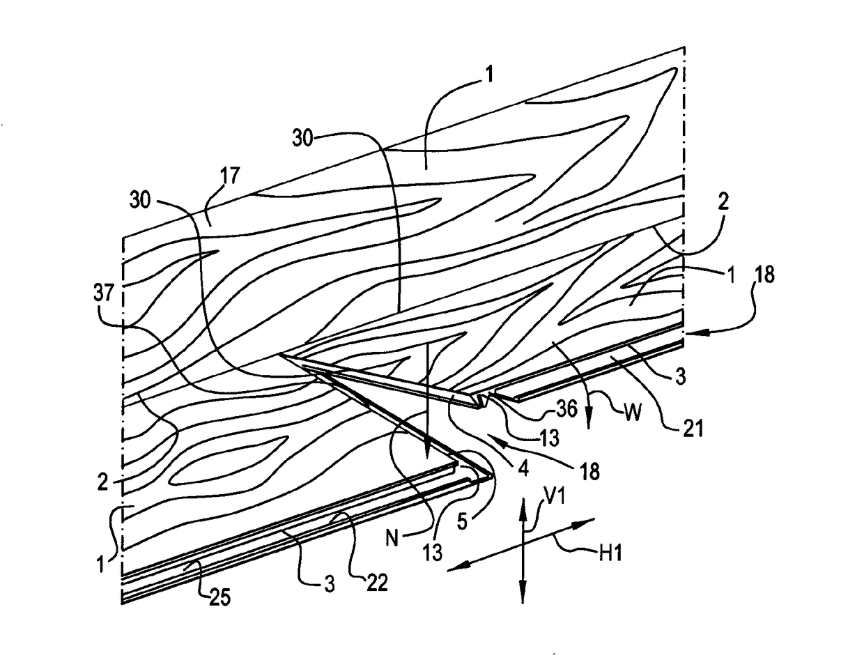
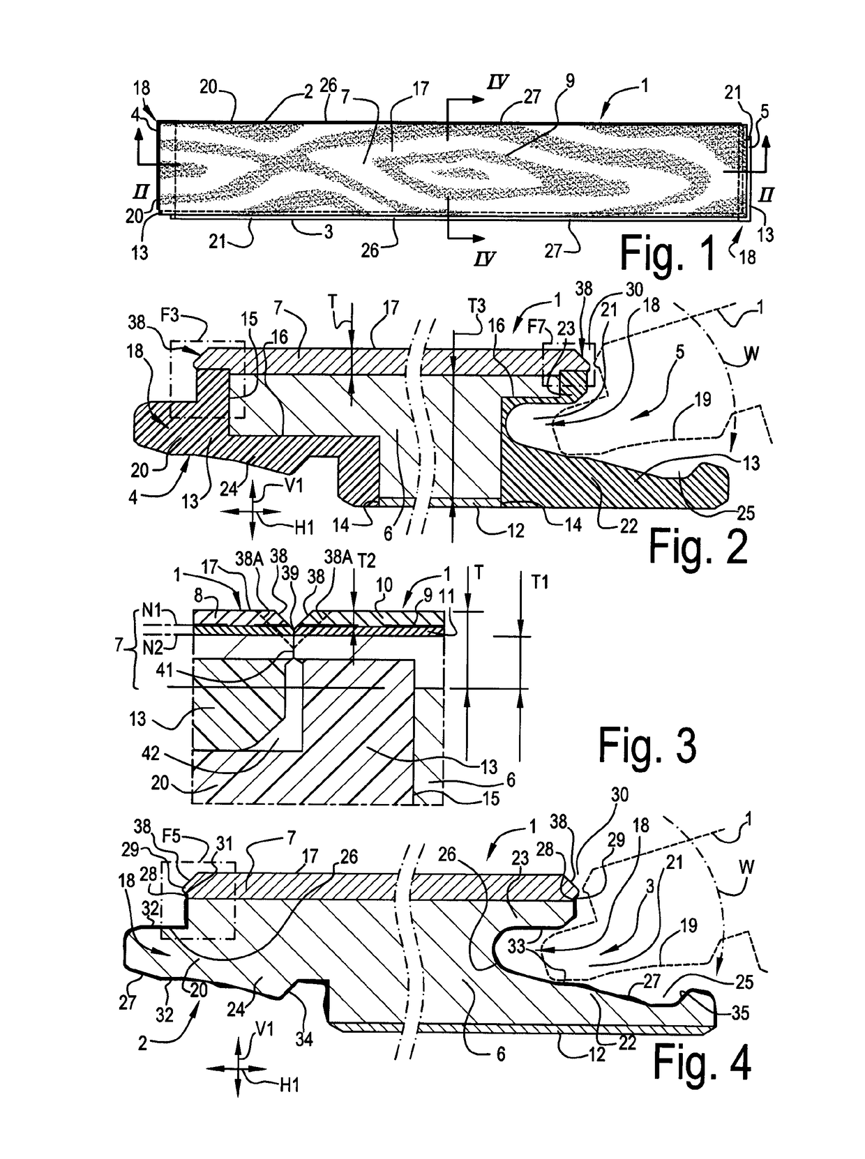
[0081]FIG. 1 represents a floor panel 1 with the characteristics of, amongst others, the first aspect of the invention. In this case, this relates to a rectangular and oblong floor panel 1 with a pair of long sides or edges 2-3 and a pair of short sides or edges 4-5.

[0082]FIG. 2 represents that the floor panel 1 is of the type which comprises at least a substrate 6 and a top layer 7 provided thereon. In the example, the top layer 7 has a thickness T of at least 0.5 millimeters. Here, specifically an annealed thermoplastic top layer is concerned, which substantially consists of PVC.

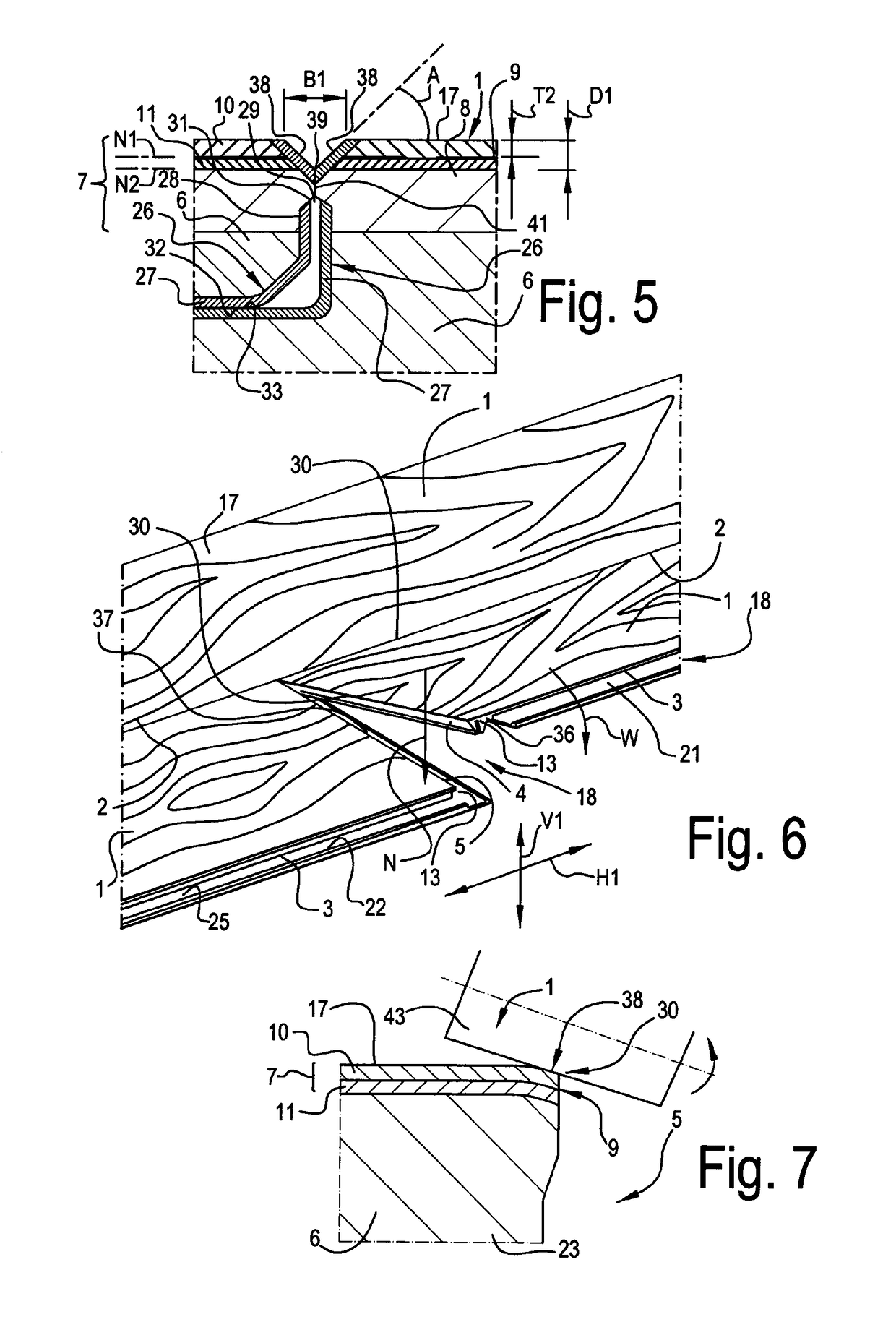
[0083]FIG. 3 shows that the thermoplastic top layer 7 preferably as such is composed of a back layer 8, a provided thereon motif 9 and a transparent thermoplastic layer or wear layer 10. Herein, the back layer 8 preferably covers a thickness T1 of more than 45 percent of the overall thickness T of the top layer 7. In this case, the back layer 8 consists of a layer of soft recycled PVC, which is filled with...


PUM

PropertyMeasurementUnit
anglesaaaaaaaaaa
lengthaaaaaaaaaa
lengthaaaaaaaaaa

Abstract

A floor panel has a rectangular and oblong shape, and includes a substrate and a top layer provided on the substrate and forming a decorative side of the floor panel. The top layer is composed of a print provided on a carrier sheet and a transparent thermoplastic layer situated above the print. The substrate has a thickness from 2 to 10 millimeter and forms at least half of the thickness of the floor panel. The substrate is a polyurethane-based substrate and the transparent thermoplastic layer is polyurethane-based. The floor panel has a length of more than 1.1 meters and has a plurality of reinforcing layers situated outside the center line of the substrate. A reinforcing layer may be provided in combination with the substrate and the top layer.

Description

[0001]This application is a continuation of U.S. Ser. No. 15 / 724,898 filed Oct. 4, 2017, which is a continuation of U.S. Ser. No. 15 / 156,520, filed May 17, 2016, now U.S. Pat. No. 9,809,984, which is a continuation of U.S. Ser. No. 14 / 552,870, filed Nov. 25, 2014, now U.S. Pat. No. 9,366,035, which claims the benefit under 35 U.S.C. 119(e) to U.S. Ser. No. 13 / 808,274 filed Jan. 4, 2013, now U.S. Pat. No. 8,925,275, and the U.S. provisional applications No. 61 / 426,734 filed on Dec. 23, 2010 and No. 61 / 429,845 filed on Jan. 5, 2011.BACKGROUND[0002]This invention relates to floor panels.[0003]More particularly, this invention relates to floor panels of the type which is at least composed of a substrate and a top layer provided on this substrate, wherein said top layer comprises a print. As known, above such motif a transparent or translucent synthetic material layer may be provided, which then forms part of said top layer.[0004]In particular, the present invention relates to panels of ...

Claims


Application Information

Patent Timeline
Patent Type & Authority Applications(United States)
IPC IPC(8): E04F15/10E04F15/02E04F15/18B27N7/00B32B3/06B32B5/18B32B7/12B32B21/02B32B21/08B32B27/08B32B27/30B32B27/32B32B27/40B44C5/04E04B1/61E04F13/08
CPCB32B2323/10E04F2201/098B32B2262/067B32B2307/412E04F15/102B32B5/18B32B7/12B32B27/32B32B27/40Y10T428/195E04F2201/049E04F2201/023E04F2201/0153E04F2201/0138E04F2201/0107E04F15/107E04F15/105E04F15/02038E04F15/02033E04B1/54B44C5/0476B44C5/043B32B2607/00B32B2255/26B32B2255/10B32B27/304B32B21/08B32B21/02Y10T428/24777Y10T428/24488Y10T428/17E04F15/18E04F2201/095E04F2201/091E04F2201/0588E04F2201/0535E04F2201/0523E04F2201/0176E04F2201/0146E04F2201/0123E04F15/02022E04F15/02E04F13/0894B32B2471/00B32B2307/712B32B2262/101B32B2260/021B32B27/08B32B3/06B27N7/00B32B2323/04E04F13/0866E04F13/18E04F2201/0115B32B37/10B32B38/145B32B2307/718B32B2309/02B32B2309/105B32B2310/0831B32B2327/06B32B2419/04B32B37/153B32B2310/0825B32B2317/16B44C1/10B32B27/30B32B2266/0235B32B2266/0278B32B2307/414B32B2307/7242B32B2307/732B32B2307/75B32B2479/00E04B1/541
Inventor MEERSSEMAN, LAURENTVANHASTEL, LUC
Owner UNILIN BV
Why Eureka
Try Eureka