
Exhaust gas purification catalyst

a technology of exhaust gas and catalyst, which is applied in the direction of physical/chemical process catalyst, metal/metal-oxide/metal-hydroxide catalyst, and separation process, etc., can solve the problems of reducing the strength reducing the power and/or fuel efficiency of the engine, and increasing the gas diffusivity of the catalyst layer, so as to achieve sufficient purification performance, the effect of enhancing the amount of exhaust gas to be purified in the catalyst coating located on

Active Publication Date: 2018-08-30
TOYOTA JIDOSHA KK +1
View PDF0 Cites 1 Cited by
  • Summary
  • Abstract
  • Description
  • Claims
  • Application Information

AI Technical Summary

Benefits of technology

The exhaust gas purification catalyst has a structure with different catalyst coatings on the upstream and downstream sides of the gas flow. The downstream side has a higher gas diffusivity, increasing the amount of exhaust gas that can be purified. This results in better purification performance even at high gas conditions. The patent is claiming priority to Japanese Patent Application No. 2015-065504.

Problems solved by technology

If a void is provided in a catalyst layer, however, the thickness of the catalyst layer is increased due to the void, and therefore the pressure loss of the catalyst may be increased to cause engine output power and / or fuel efficiency to be lowered.
In addition, the void provided by any of the above methods has the following problem, for example: the strength of the catalyst layer is decreased, or a sufficient effect is not obtained because of poor void linkage.

Method used


Image

  • Exhaust gas purification catalyst
  • Exhaust gas purification catalyst
  • Exhaust gas purification catalyst

Examples


examples

[0100]Hereinafter, the present invention will be described in more detail with reference to Examples, but the present invention is not intended to be limited to these Examples.

examples 2 to 42

(2) Examples 2 to 42

[0107]Each catalyst slurry was obtained in the same manner as in Example 1 except that the treatment time by a bead mill was changed as shown in Table 1 and Table 2, the stirring treatment was performed by a bead mill so that the particle size of the metal oxide particle was as shown in Table 1 and Table 2 in terms of the 50% cumulative size in a cumulative particle size distribution on a volume basis, and a fibrous organic substance, the type of a raw material, the average fiber diameter, the average aspect ratio and the amount mixed of which were as shown in Table 1 and Table 2, was used as the fibrous organic substance. Next, a cordierite monolith honeycomb substrate was coated with the resulting catalyst slurry in the same manner as in Example 1, and the resultant was fired to provide an exhaust gas purification catalyst (catalyst sample).

[0108]Herein, each fibrous organic substance used in Examples 31 to 39 was prepared by adding titanium isopropoxide (Ti(OP...


PUM

PropertyMeasurementUnit
thicknessaaaaaaaaaa
aspect ratioaaaaaaaaaa
equivalent circle diameteraaaaaaaaaa

Abstract

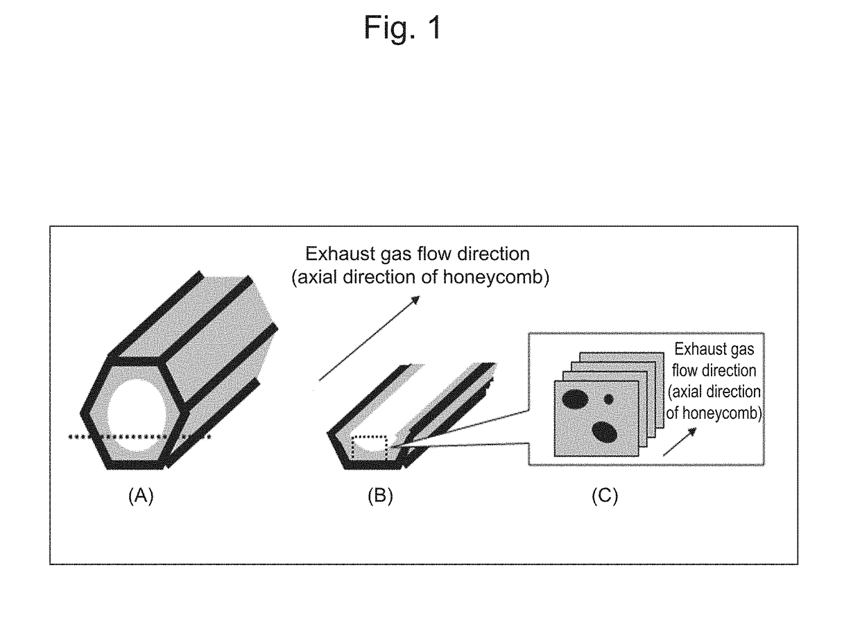
An object of the present invention is to provide an exhaust gas purification catalyst which can exhibit sufficient purification performance even under a high Ga condition. The present invention relates to an exhaust gas purification catalyst comprising a substrate and a catalyst coating layer formed on the substrate, wherein the catalyst coating layer comprises catalyst particles, the catalyst coating layer having an upstream region extending by 40 to 60% of the entire length of the substrate from an upstream end of the catalyst in the direction of an exhaust gas flow and a downstream region corresponding to the remainder portion of the catalyst coating layer, the composition of the catalyst particle of the upstream region being different from that of the downstream region. The downstream region in the direction of an exhaust gas flow has a structure where a void is included in a large number, and furthermore high-aspect-ratio pores having an aspect ratio of 5 or more account for a certain percentage or more of the whole volume of voids. Thus, the exhaust gas purification catalyst exhibits enhanced purification performance.

Description

TECHNICAL FIELD[0001]The present invention relates to an exhaust gas purification catalyst. More specifically, it relates to an exhaust gas purification catalyst comprising a catalyst coating layer different in composition between a region located on an exhaust gas upstream side and a region located on an exhaust gas downstream side, wherein a catalyst coating located on an exhaust gas downstream side has a high-aspect-ratio pore at a certain rate.BACKGROUND ART[0002]Exhaust gas discharged from an internal combustion engine of an automotive or the like includes harmful gases such as carbon monoxide (CO), nitrogen oxides (NOx), and unburned hydrocarbon (HC). An exhaust gas purification catalyst for decomposition of such harmful gases is also referred to as a “three-way catalyst”, and commonly has a honeycomb-shaped monolith substrate made of cordierite or the like and a catalyst coating layer formed thereon by wash coating of a slurry including a noble metal particle having catalyst ...

Claims


Application Information

Patent Timeline
Patent Type & Authority Applications(United States)
IPC IPC(8): B01D53/94B01J23/56B01J35/00B01J35/02B01J35/04B01J35/10B01J37/02B01J37/08F01N3/10F01N3/28
CPCB01D53/945B01D53/9468B01D53/9472B01J23/56B01J35/0006B01J35/023B01J35/026B01J35/04B01J35/10B01J35/1076B01J37/0219B01J37/08F01N3/101F01N3/28B01D2255/1021B01D2255/407B01D2255/9032B01D2255/9022B01D2255/1023B01D2255/1025B01D2255/9202B01D2255/9205F01N2510/0682B01J23/63B01J37/0234B01J37/0018B01J37/0036B01D2255/10B01D2255/2063B01J37/0244Y02T10/12B01J35/50B01J35/19B01J35/40B01J35/56B01J35/60B01J35/657B01J35/66B01D53/94
Inventor SUZUKI, HIROMASAMIURA, MASAHIDESAITO, YOSHINORIKATOH, SATORUTANABE, TOSHITAKAHIRAO, TETSUHIROOHASHI, TATSUYANAITO, HIROAKIORI, HIROTAKATAKEUCHI, MICHIHIKONARITA, KEIICHI
Owner TOYOTA JIDOSHA KK
Learn More