Chamfering tool with guide for eliminating vibrations

Active Publication Date: 2018-08-23
RATTUNDE
View PDF6 Cites 0 Cited by
  • Summary
  • Abstract
  • Description
  • Claims
  • Application Information

AI Technical Summary

Benefits of technology

This patent describes a cutting machine for machining tube section ends that reduces vibrations and avoids regenerative chatter. The machine has a support component with an annular component that rotates about the machine's axis. The annular component is interchangeable, and its rotation decreases the angular velocity of the machine, reducing the load on the spindle that rotates the tool head. This results in a cutting machine that is easy to maintain and has improved efficiency.

Problems solved by technology

If the load changes are in the region of the natural frequency of the tool head mounted on the spindle, undesirable chatter can ensue.
On the one hand the chatter subjects the cutting machine to loading, and on the other hand the tube section end to be produced is corrugated, and losses of quality ensue.
The tube section end to be machined may even become unusable.
This results in chatter which is increasingly intensive.
In the case of tools with a single cutter, naturally, a change of the cutter spacing is not possible.
However, it is known that a rotational speed of the rotating cutting tool is continuously changed quickly, but in the case of high frequencies this leads to substantial loading of the machine.
However, the said systems for preventing the regenerative chatter are exceptionally elaborate and also require intensive maintenance.

Method used


Image

  • Chamfering tool with guide for eliminating vibrations
  • Chamfering tool with guide for eliminating vibrations
  • Chamfering tool with guide for eliminating vibrations

Examples


Embodiment Construction

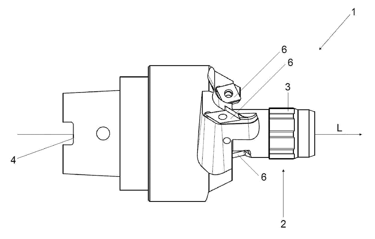
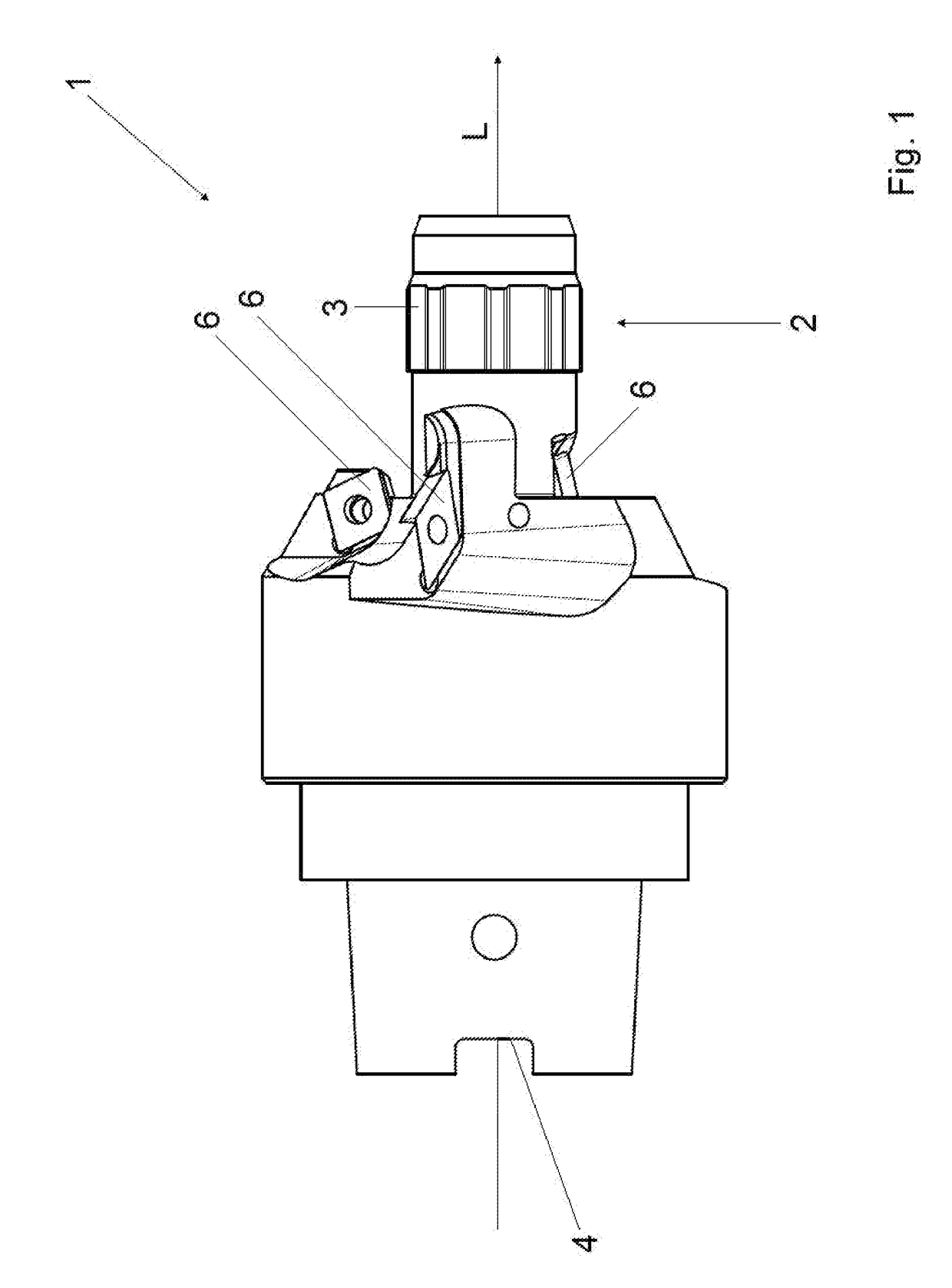
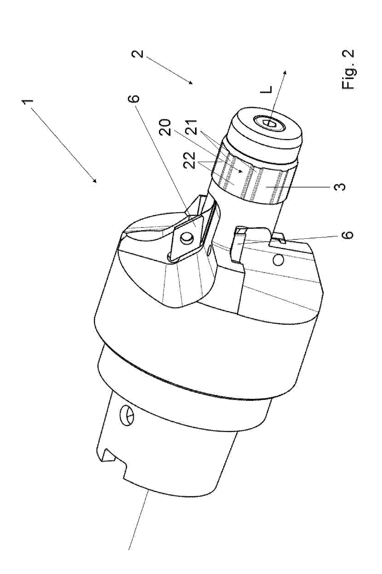
[0038]A tool head 1 illustrated in FIG. 1 additionally has a mandrel 2 projecting with respect to tool heads, which are known for example from EP 2 106 313 B1, along a longitudinal axis L of the tool head, an annular component 3 being rotatably mounted on the outer end of the mandrel. The annular component 3 and the mandrel 2 are substantially circular in cross-section perpendicular to the longitudinal axis L and are arranged concentrically around the longitudinal axis L of the tool head 1. On one end of the tool head 1 opposite the mandrel 2 a spindle receiving area 4 is provided, by which the tool head 1 is interchangeably fastened on a spindle (not shown) in a controlled manner.

[0039]The tool head 1 in FIG. 1 has four cutting plates 6, of which three can be seen in FIG. 1. The cutting plates 6 are intended for machining of a tube section end 40 which in cross-section has a circular internal diameter and a circular external diameter. Two of the cutting plates 6 are intended for ap...


PUM

PropertyMeasurementUnit
Diameteraaaaaaaaaa
Speedaaaaaaaaaa
Shapeaaaaaaaaaa

Abstract

The invention relates to a cutting machine with a receiving area for a tube section and with a tool head (1) which can be rotated relative to the receiving area about a longitudinal axis (L), has at least one cutting tool (6) for machining a tube section end (40) of the tube section located in the receiving area, and has a support component (2), wherein the support component faces the receiving area and has an annular component (3) which rotates relative to the support component (2) about the longitudinal axis (L) and is designed to be randomly supported on a tube wall (42, 42) of the tube section end (40). The invention further relates to a corresponding method for reducing vibrations.

Description

CROSS REFERENCE TO RELATED PATENT APPLICATIONS[0001]This patent application is filed herewith for the U.S. National Stage under 35 U.S.C. § 371 and claims priority to PCT application PCT / EP2016 / 076303, with an international filing date of Nov. 1, 2016. The contents of this application are incorporated in their entirety herein.BACKGROUND OF THE INVENTION[0002]The invention relates to a cutting machine and a method for reduction in particular of regenerative chatter of the cutting machine.[0003]Cutting machines are well known in the prior art in the form of rotating tool heads for tube ends. A tool head is disclosed for example in EP 2 106 313 B1.[0004]DE 2541414 discloses a tool which can be actuated manually for chamfering of a tube end. The tool is actuated at a low rotational speed. The tool is guided by radially outer parts which extend beyond the cutting edges, as well as a guide means on which rotatable discs are fitted.[0005]Cutting machines with rotating tool heads are bodies...

Claims


Application Information

Patent Timeline
IPC IPC(8): B23B5/16
CPCB23B5/168B23B2250/16B23B2260/008
Inventor RATTUNDE, ULRICH
Owner RATTUNDE
Why Eureka
Try Eureka