Bevel processing method and the cutting tool used

A processing method and technology of chamfering, which are applied in the direction of tools, manufacturing tools, metal processing equipment, etc. for lathes, which can solve the problems of reducing processing accuracy, and achieve the goal of improving processing accuracy, reducing knife vibration, and improving product yield. Effect

Inactive Publication Date: 2017-03-01
FU DING ELECTRONICSAL TECH JIASHAN +2
View PDF7 Cites 0 Cited by
  • Summary
  • Abstract
  • Description
  • Claims
  • Application Information

AI Technical Summary

Problems solved by technology

However, the mechanical arm and the tool are prone to position deviation before and after adjusting the angle, resulting in chattering lines on the inclined surface, which reduces the machining accuracy

Method used


Image

  • Bevel processing method and the cutting tool used
  • Bevel processing method and the cutting tool used
  • Bevel processing method and the cutting tool used

Examples


Embodiment Construction

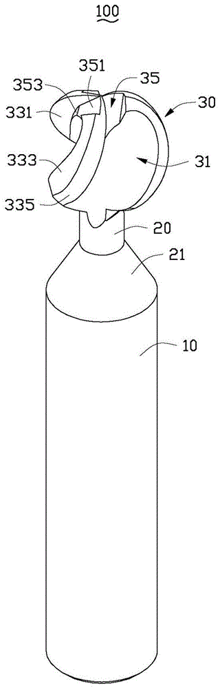
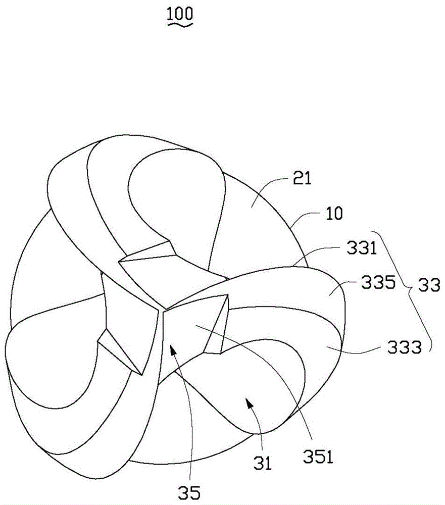
[0030] see figure 1 and figure 2 , the chamfer processing method of the embodiment of the present invention adopts cutter 100 to workpiece 200 (refer to Figure 4 ) for processing. The tool 100 includes a tool bar 10 , a relief portion 20 and a tool body 30 . The avoidance part 20 connects the knife rod 10 and the knife body 30 . The escape portion 20 is smaller in diameter than the cutter bar 10 and forms an inverted tapered surface 21 at the connection with the cutter bar 10 . The cutter body 30 is substantially spherical, and its diameter is larger than that of the cutter shaft 10 . It can be understood that the cutter body 30 can also be an ellipsoid, a T-shaped angle round nose cutter or a T-shaped ball cutter.

[0031] Three grooves 31 are evenly spaced along the periphery of the cutter body 30 to form three cutting portions 33 . The groove 31 extends away from the cutter rod 10 at an angle of 30 degrees to the axial direction of the cutter rod 10 . The cross-sec...


PUM


Abstract

Disclosed is a chamfer machining method. The chamfer machining method includes the following steps that a tool comprising a tool bar, a spherical tool body and an avoiding portion connected with the tool bar and the tool body is provided, the tool body is provided with multiple grooves along the periphery, a cutting portion is formed between every two adjacent grooves, and each cutting portion comprises a rake surface facing one groove, a flank surface connected with the other groove and a connecting surface connected with the rake surface and the flank surface; a workpiece comprising a side face is positioned; the tool is driven to drive the cutting portions of the tool body to butt against the side face of the workpiece; the tool is driven to drive the tool body to rotate around an axis thereof, the edges of the rake surfaces are allowed to machine the side face of the workpiece in a point contact mode, and the tool body is driven to move along the preset route so as to machine a chamfer. By the chamfer machining method, vibration tool lines are reduced effectively, machining precision is improved, and product yield is increased. The invention further provides the tool applied to the method.

Description

technical field [0001] The invention relates to a method for processing an inclined surface, in particular to a method for processing an inclined surface and a cutting tool used therefor. Background technique [0002] In the industry, traditional five-axis robotic arms are often used to drive tools to process chamfered surfaces. In order to avoid workpiece interference, there are certain restrictions on the stroke of the tool and the robot arm. When machining various parts of the bevel, it is necessary to adjust the machining angle of the robot arm and the tool in real time. However, the mechanical arm and the tool are prone to position deviation before and after adjusting the angle, which will cause chatter lines on the chamfered surface and reduce the machining accuracy. Contents of the invention [0003] In view of the above, it is necessary to provide a method for machining chamfered surfaces with high machining accuracy and the cutting tool used therein. [0004] A...

Claims


Application Information

Patent Timeline
IPC IPC(8): B23D79/00B23B27/00
Inventor 陈封华瞿健葛杨东
Owner FU DING ELECTRONICSAL TECH JIASHAN
Why Eureka
Try Eureka