Endless belt

Active Publication Date: 2006-10-24
MAGUIRE SUPER SHIELD
View PDF13 Cites 23 Cited by
  • Summary
  • Abstract
  • Description
  • Claims
  • Application Information

AI Technical Summary

Benefits of technology

[0006]Since the medial portion of the flight is rearwardly offset from the portions immediately lateral to it, the flight forms a natural “cup” that helps brings objects towards and holds objects in a central region of the belt. When the endless belt is disposed above a conveyor belt, for example a conveyor belt of a stone slinger, such an arrangement of flights on the endless belt provides much better control of objects being transported on the conveyor belt. Premature and erratic discharge of objects is greatly reduced as the objects are guided toward and held in the center of the conveyor belt by the endless belt.
[0019]Objects that may be transported on a conveyor belt and controlled on the conveyor belt by an endless belt of the present invention are any relatively solid object, for example, vegetables (e.g. beans, potatoes, etc.) and particulate matter (e.g. stones, sand, rocks, gravel, etc.). Endless belts of the present invention are preferably used on control apparatuses for conveyors of particulate material (e.g. stone slingers). Such control apparatuses are described in U.S. Pat. No. 6,241,076 issued Jun. 5, 2001, U.S. Pat. No. 6,615,976 issued Sep. 9, 2003 and U.S. Pat. No. 6,695,125 issued Feb. 24, 2004, the disclosures of which are herein incorporated by reference in their entirety. The endless belt of the present invention advantageously provides unexpected improvement in the control of larger volumes of objects, in the control of a greater selection of object shapes, in the control of objects in a wider variety of weather conditions, or in any combination of the above. In the case of stone slingers, increased control over objects on the conveyor belt leads to an advantageous improvement in throw distance and accuracy.

Problems solved by technology

Particulate material on the thrower belt has a tendency to bounce around and be thrown off in a premature and / or erratic manner.
This belt is designed to actually carry particulate material, hence the troughing of the belt, and would be poorly effective in a control apparatus for a stone slinger.
If used in a control apparatus on a stone slinger, the “waviness” of the belt would detrimentally affect object control as it would permit objects to escape off the sides of the thrower belt and objects would collect in several regions rather than just one.
If used on a control apparatus for a stone slinger, this belt would allow objects to slip back through the gap thus losing throwing effectiveness and control.
Thus, the aforementioned belts are not well suited for use on a control apparatus positioned above particulate material for controlling particulate material on a thrower belt of a stone slinger.
Furthermore, these belts, and other conveyor belts like them are flat on the underside and do not have means on the underside to permit engagement with rotational elements.

Method used


Image

  • Endless belt
  • Endless belt
  • Endless belt

Examples


Embodiment Construction

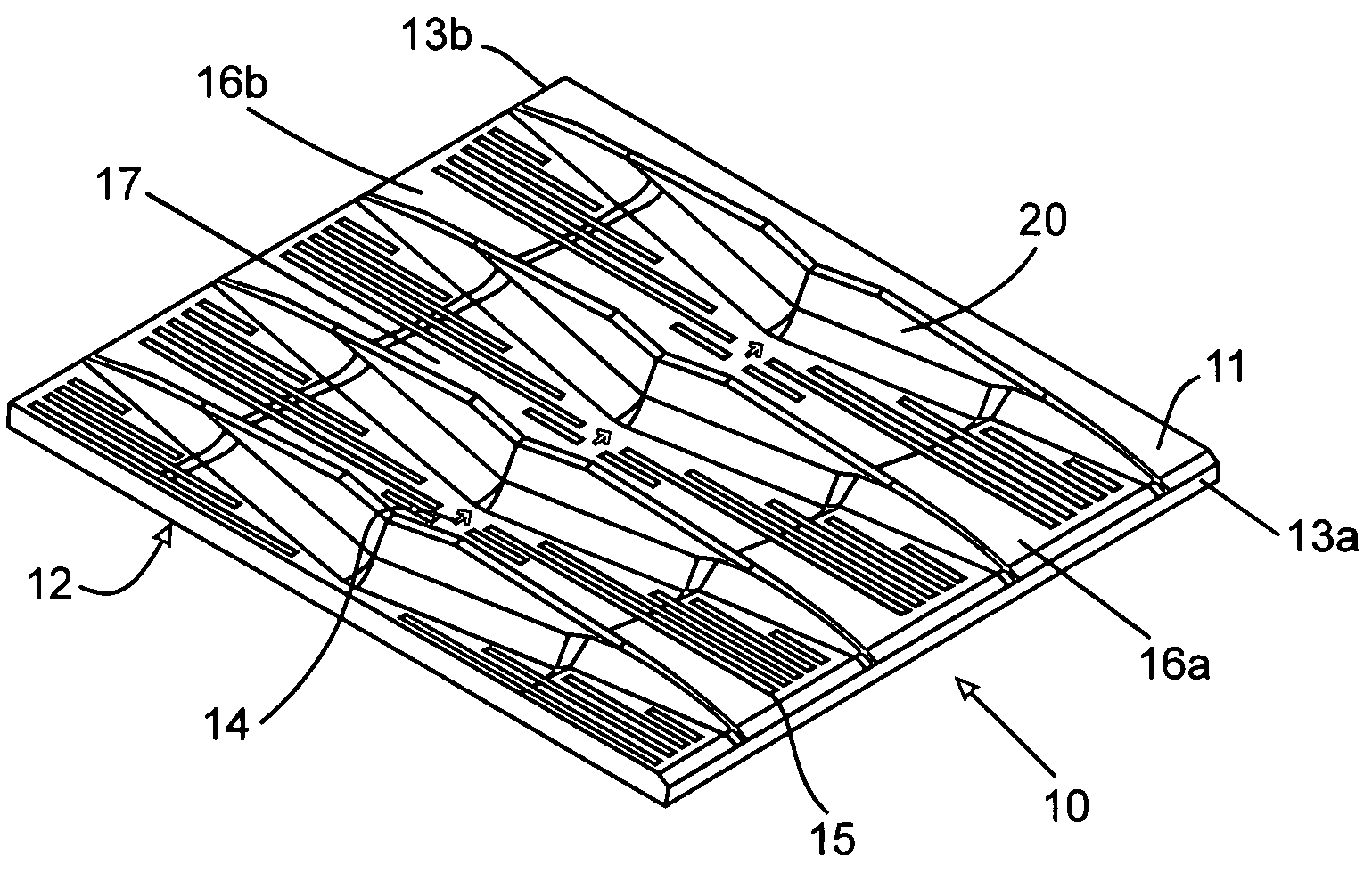
[0028]Referring to FIG. 1, a section of endless rubber belt 10 comprises outer surface 11 and inner surface 12. Molded integrally with outer surface 11 are a plurality of longitudinally spaced-apart laterally oriented upraised chevron-shaped flights 20 (four shown and one labeled) extending across the width of the belt from first lateral edge 13a to second lateral edge 13b. Forward longitudinal direction (i.e. direction of travel) of the endless belt is shown by arrows 14 molded into outer surface 11. A plurality of laterally-extending grooves 15 (only one labeled) between flights 20 permit the belt to flex more readily without breaking or delaminating. First and second lateral regions 16a,16b of the endless belt are 0.125 inch higher than central region 17, the central region being depressed relative to the lateral regions as better illustrated in FIG. 4. Lateral edges 13a,13b are integrally molded with the rubber outer and inner surfaces to seal the cloth casing of the belt betwee...


PUM


Abstract

A flexible endless belt mountable on rotating elements has an outer and inner surface between first and second lateral edges and a plurality of longitudinally spaced-apart laterally oriented upraised flights on the outer surface. Each flight has a single medial portion offset in a rearward longitudinal direction from portions of the flight immediately lateral to the medial portion. Protrusions on the inner surface engage the rotating elements for endlessly rotating the endless belt in a forward longitudinal direction. Such an endless belt is particularly useful on a control apparatus for a stone slinger.

Description

FIELD OF THE INVENTION[0001]The present invention is related to endless belts, preferably endless belts for assisting in transporting particulate material.BACKGROUND OF THE INVENTION[0002]Conveyors for moving particulate material, such as stone, gravel, sand, and the like, are known in the art. Such conveyors, commonly called “stone slingers”, generally comprise a thrower belt mounted on a truck, the truck having a storage hopper for holding the particulate material. Particulate material is dispensed from the hopper on to the thrower belt and then transported along the thrower belt to be deposited in a desired locating remote from the truck.[0003]Particulate material on the thrower belt has a tendency to bounce around and be thrown off in a premature and / or erratic manner. To control the flow of particulate material on the thrower belt, an endless belt positioned above the thrower belt may be used. Such an arrangement is disclosed in U.S. Pat. No. 6,241,076 issued Jun. 5, 2001, U.S....

Claims


Application Information

Patent Timeline
IPC IPC(8): B65G13/02
CPCB65G15/42B65G2201/045
Inventor MAGUIRE, DENNIS R.
Owner MAGUIRE SUPER SHIELD
Why Eureka
Try Eureka