Device for securing a boring bar

A fixing device, boring bar technology, applied in the direction of tools for lathes, boring bars, accessories for tool holders, etc.

Active Publication Date: 2020-10-30
胡贝特基米希
View PDF9 Cites 0 Cited by
  • Summary
  • Abstract
  • Description
  • Claims
  • Application Information

AI Technical Summary

Problems solved by technology

It has been shown here that when turning cylindrical cavities, the distance between the inner wall of the cavity and the outer wall of the hollow profile is too small for deep and narrow cavities to be turned without the hollow profile colliding with the cavity

Method used


Image

  • Device for securing a boring bar
  • Device for securing a boring bar
  • Device for securing a boring bar

Examples


Embodiment Construction

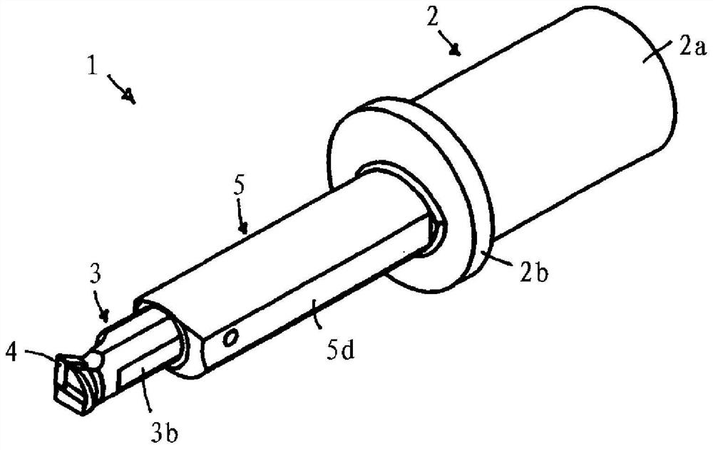
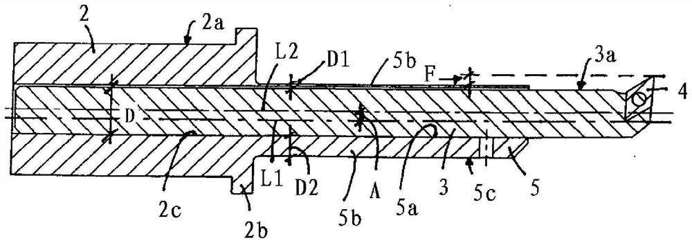
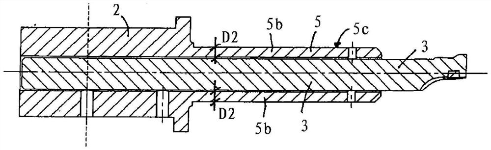
[0032] The device 1 according to the invention for fixing a boring bar 3 on a cutting machine (machine not shown) has a reducing sleeve (clamping sleeve) 2 with a cylindrical outer peripheral surface 2a, by means of The outer peripheral reducing sleeve can be fixed in the cylindrical recess of the machine chuck. The reduction sleeve has an optional flange 2b on the outer end. Furthermore, the reducing sleeve 2 has an inner longitudinal recess 2c, into which a boring bar 3 is inserted in a form-fitting, longitudinally adjustable manner, the outer peripheral surface 3a of which is cylindrical, so that the longitudinal direction of the reducing sleeve 2 The recess 2c is also cylindrical with the same diameter D. As shown in FIG. The reducing sleeve (clamping sleeve) 2 thus has the same longitudinal axis L2 as the boring bar 3 and the longitudinal recess 5 a of the hollow profile 5 .

[0033] in accordance with Figures 1 to 3 In the exemplary embodiment, the outer peripheral s...


PUM


Abstract

The invention relates to a securing device (1) for securing a boring bar (3) to a machining tool, the device comprising a cylindrical reduction sleeve (2) that can be secured in the tool chuck, the front end of which sleeve furthest away from the tool chuck having a protruding hollow section (5) with an interior running coaxially with the axis of the reduction sleeve (2), in particular a cylindrical interior that receives the boring bar (3), wherein: an end region of the boring bar (3), protruding from the hollow section (5), supports a cutting tool (4); the wall (5b) of the boring-bar-stabilising hollow section (5), between the hollow-section interior (5a) and the hollow-section outer wall, has a lesser thickness (D1) in the side region of the device, in which the cutting tool (4) protrudes on the boring bar (3), than the thickness (D2) of the rest of the wall of the hollow section (5); and the longitudinal axis (L1) of the hollow section (5) runs axially parallel to and at a distance(A) from the common axis (L2) of the reduction sleeve (2) and the boring bar (3).

Description

technical field [0001] The invention relates to a device for fixing a boring bar on a cutting machine, comprising a cylindrical reducing sleeve capable of being fixed in a machine chuck, at the front end of the reducing sleeve, i.e. facing away from the machine chuck A hollow profile protrudes from the end of the disk, the in particular cylindrical interior of which is coaxial to the axis of the reducing sleeve, accommodates a boring bar, the end region of which protrudes from the hollow profile with the tool. Background technique [0002] Such a device is known from JP 3151632 U. It has been shown here that, when turning cylindrical cavities, the distance between the inner wall of the cavity and the outer wall of the hollow profile is too small, so that deep and narrow cavities cannot be turned without the hollow profile colliding with the cavity. Contents of the invention [0003] The object of the present invention is to improve a device of the type mentioned at the ou...

Claims


Application Information

Patent Timeline
Patent Type & Authority Applications(China)
IPC IPC(8): B23B29/04B23B27/00B23B31/107
CPCB23B27/007B23B31/1075B23B29/04B23B29/02B23B29/022
Inventor 胡贝特·基米希
Owner 胡贝特基米希
Why Eureka
Try Eureka