
Thin fan and thin-plate motor

a thin-plate motor and fan technology, applied in the direction of machines/engines, mechanical equipment, liquid fuel engines, etc., can solve the problems of unstable rotation of the rotor structure, poor vibration duration, unstable rotor shell manufacturing process, etc., to increase the entire manufacturing stability, improve assembly accuracy, and reduce the process and cost of manufacturing the thin fan or thin-plate motor.

Inactive Publication Date: 2018-08-16
DELTA ELECTRONICS INC
View PDF14 Cites 1 Cited by
  • Summary
  • Abstract
  • Description
  • Claims
  • Application Information

AI Technical Summary

Benefits of technology

The patent describes a thin fan or thin-plate motor with a single component manufactured by processing a single material workpiece. This design improves the assembly accuracy and manufacturing yield, reducing the need for laser welding and reducing costs. The rotor structure has groove structures, dynamic patterns, or thrust patterns formed on its surface through an additional turning process, and an oil repellent layer is formed on the surface of the rotor shell to prevent oil leakage. These features improve the operation efficiency and lifetime of the thin fan or thin-plate motor.

Problems solved by technology

In the conventional thin fan or thin-plate motor, the rotor shell and shaft of the rotor structure are connected by laser welding due to the limitation of the thickness of the rotor shell.
However, the laser welding may cause the unstable of the manufacturing process of the rotor shell, the oil leaking of the rotor shell, the unstable rotation of the rotor structure, and the poor vibration duration.
Since the rotor shell and the shaft are individual parts, the connection thereof will have the above mentioned problems.
Besides, the thickness of the rotor shell has limitation, the size of the fan or motor cannot be thinner.
However, the rotor shell made by the stamping process may have assembling error and unstable rotation due to the processing tolerances on, for example, the flatness of the magnetic surface, the accuracy of the inner diameter of the rotor shell, and the draft angle.
In particular, the gaps between the components of the ultra-thin fan or ultra-thin-plate motor are very small.
Any of the above processing tolerances will cause a very serious interference in the rotation of the rotor structure, and will sufficiently increase the difficulty in the following manufacturing processes and assembling.

Method used


Image

  • Thin fan and thin-plate motor
  • Thin fan and thin-plate motor
  • Thin fan and thin-plate motor

Examples


Embodiment Construction

[0035]The present invention will be apparent from the following detailed description, which proceeds with reference to the accompanying drawings, wherein the same references relate to the same elements.

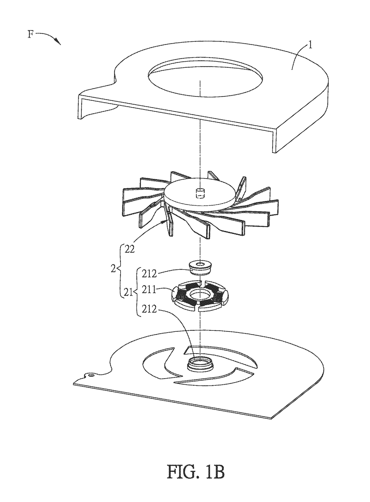
[0036]FIG. 1A is a schematic diagram showing a thin fan according to an embodiment of the disclosure, FIG. 1B is an exploded view of the thin fan of FIG. 1A, and FIG. 1C is a sectional view of the thin fan of FIG. 1A along the line A-A.

[0037]As shown in FIGS. 1A to 1C, the present disclosure provides a thin fan F, which includes a frame 1 and a driving device 2 disposed in the frame 1. The driving device 2 includes a stator structure 21 and a rotor structure 22. The stator structure 21 includes a stator pole group 211 and a base body 212. The base body 212 is connected to the frame 1, and the stator pole group 211 is disposed on an outer periphery of the base body 212. The rotor structure 22 is disposed corresponding to the stator structure 21. The rotor structure 22 includes a rotor ...


PUM


Abstract

A thin fan includes a frame and a driving device disposed in the frame. The driving device includes a stator structure and a rotor structure. The stator structure includes a stator pole group and a base body connected to the frame. The stator pole group is disposed on the outer periphery of the base body. The rotor structure is disposed corresponding to the stator structure, and includes a rotor shell, a magnetic structure and an impeller connected to the rotor shell. The center of the rotor shell is formed with a cylindrical shaft, which deeply penetrates into the base body. The rotor shell and the shaft are a single component manufactured by processing a single material workpiece. The magnetic structure is disposed on the inner wall of the rotor shell, and the stator magnetic pole group magnetically drives the magnetic structure as well as the rotor shell to rotate.

Description

CROSS REFERENCE TO RELATED APPLICATIONS[0001]The non-provisional patent application claims priority to U.S. provisional patent application with Ser. No. 62 / 458,688 filed on Feb. 14, 2017. This and all other extrinsic materials discussed herein are incorporated by reference in their entirety.[0002]This Non-provisional application claims priority under 35 U.S.C. § 119(a) on Patent Application No(s). 201710494155.9 filed in People's Republic of China on Jun. 26, 2017, the entire contents of which are hereby incorporated by reference.BACKGROUND OF THE INVENTIONField of Invention[0003]The present disclosure relates to a thin fan and a thin-plate motor that have an integrally formed rotor shell and shaft.Related Art[0004]In the existing electronic device, the heat dissipation efficiency is one of the major factors to determine the performance and lifetime of the electronic device. In general, the electronic device is provided with a fan for dissipating the generated heat. In more detailed...

Claims


Application Information

Patent Timeline
Patent Type & Authority Applications(United States)
IPC IPC(8): F04D25/08H02K5/16F04D29/054F04D29/056F04D29/62H02K5/18H02K9/06
CPCF04D25/08H02K5/165F04D29/054F04D29/056F04D29/626H02K5/18H02K9/06F04D17/16F04D25/0606F04D25/0613H02K5/1675H02K7/14
Inventor YEH, CHENG-HSIENCHAN, CHIH-WEI
Owner DELTA ELECTRONICS INC
Learn More