Vehicle control system and method

Active Publication Date: 2018-07-05
GE GLOBAL SOURCING LLC
View PDF0 Cites 16 Cited by
  • Summary
  • Abstract
  • Description
  • Claims
  • Application Information

AI Technical Summary

Benefits of technology

The patent describes a control system for a vehicle that uses energy storage devices to power motors and travel along a route. The system determines if there is not enough stored energy to power the vehicle through certain segments of the route and takes appropriate action to ensure the vehicle can still travel through those segments. This can include switching which energy storage device powers the motors, changing the speed or torque of the motors, changing the route, reducing the number of motors, requesting additional electric current, drawing electric current from the energy storage devices, activating a fuel-consuming motor, drafting or mechanically coupling to another vehicle, or controlling the vehicle to gain momentum or generate an overcharge. The technical effect of this system is to enable the vehicle to travel more efficiently and effectively along the route, even when there are certain segments that do not have a catenary or electrified rail to power the motors.

Problems solved by technology

Because of the changing load of the vehicles, the amount of tractive force needed to move the vehicle can change over time.
But, some known vehicles keep all traction motors actively generating tractive force to propel the vehicles, even if some of the traction motors are generating a relatively small amount of tractive force.
Because the simulations are performed prior to embarking on a trip, these consists are unable to adapt to changing conditions during movement.
For example, the consists are not able to turn any traction motors on or off based on a real time change in the needed tractive forces that was not present in the simulations.
The costs of running such vehicles are dependent, typically, on local fuel costs.
Thus, during some time periods (e.g., peak demand periods), costs may actually be higher.
Additionally, the infrastructure for providing wayside electricity may be expensive, due to having to provide sufficient capacity for peak demands.
But, adding such wayside sources can be time-consuming and costly.

Method used


Image

  • Vehicle control system and method
  • Vehicle control system and method
  • Vehicle control system and method

Examples


Embodiment Construction

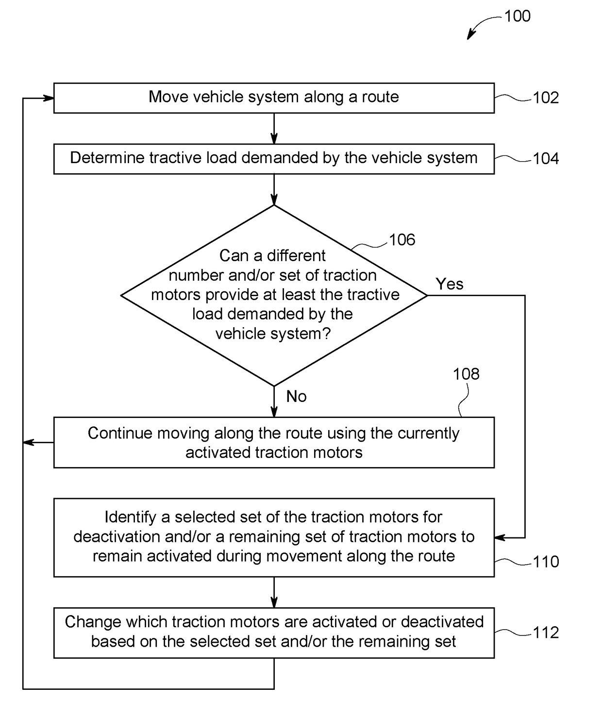
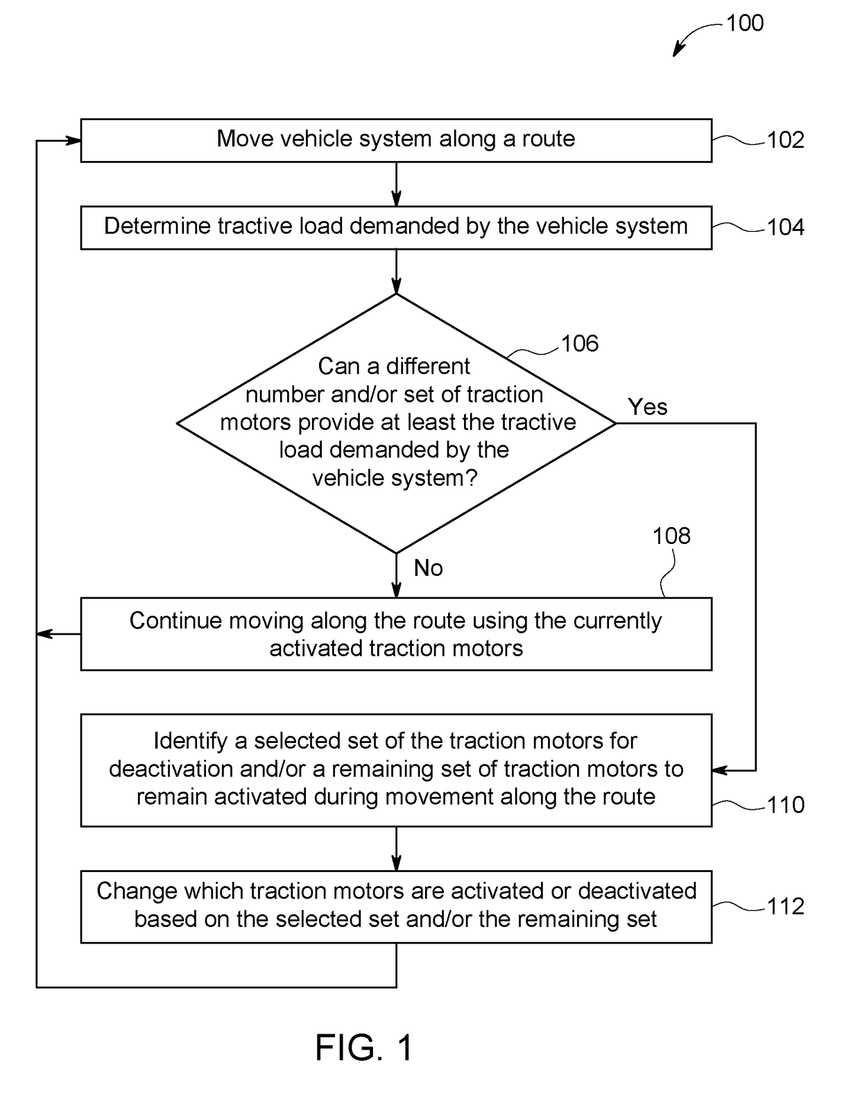
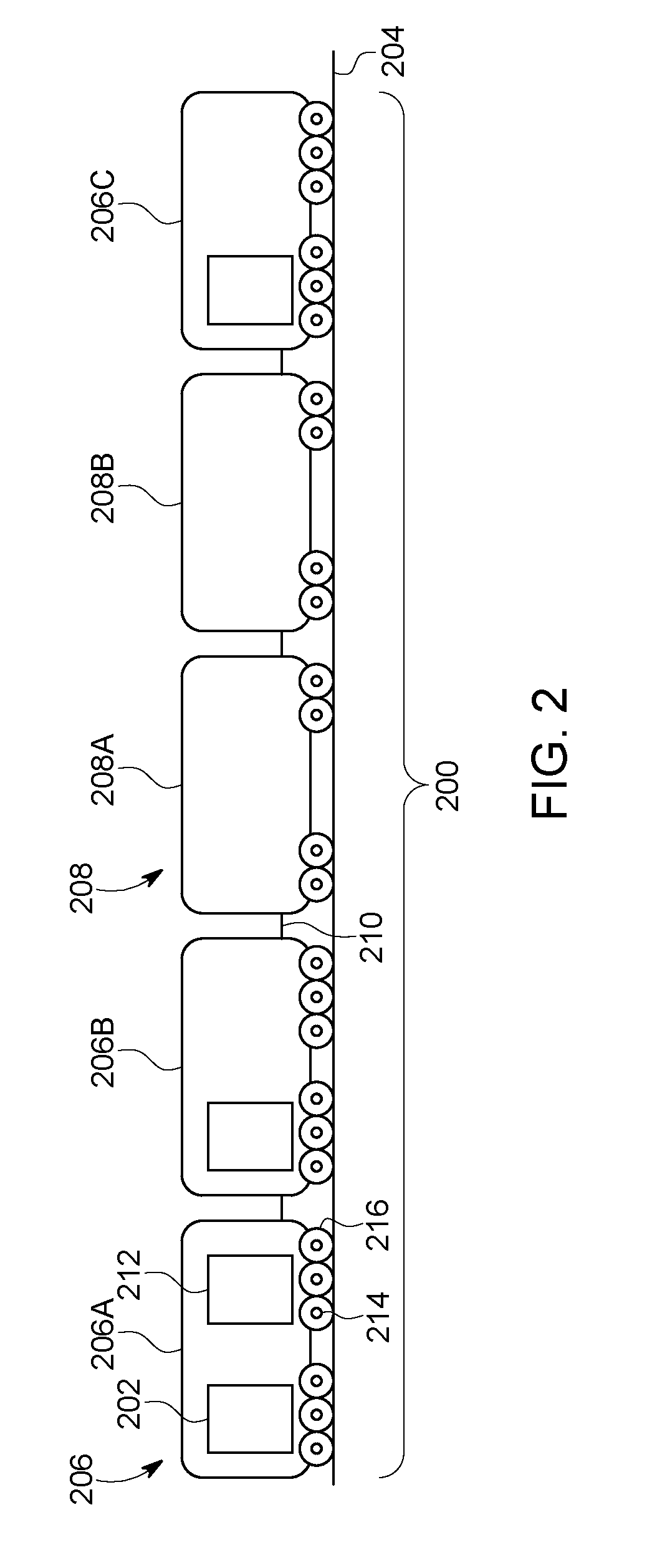
[0029]One or more embodiments described herein provide systems and methods for individually controlling which traction motors in a vehicle having multiple traction motors are activated or deactivated at different times during movement of the vehicle. The different traction motors of the vehicle can be operably coupled with different axles and / or wheel sets of the vehicle such that the activated traction motors work to rotate the axles and / or wheel sets to propel the vehicle while the deactivated traction motors do not work to rotate the axles and / or wheel sets. The vehicle can be included in a larger vehicle system having one or more other vehicles connected with each other, such as a vehicle consist. During movement along a route, a tractive load demanded to propel the vehicle system along the route can be determined. This tractive load can be compared to the capabilities of the traction motors to produce tractive effort. If fewer than all of the traction motors in a vehicle can be...


PUM


Abstract

A vehicle control system controls operation of motors of a vehicle and determines whether there is sufficient stored electric energy to power the vehicle through an unpowered segment of a route. The controller changes operation of the vehicle to ensure that the vehicle can travel completely through the unpowered segment by switching which energy storage device provides energy, changing vehicle speed, changing motor torque, changing which route is traveled on, selecting fewer motors to power the vehicle, requesting rendezvous with a recharging vehicle, running the energy storage devices in a degraded mode, initiating a motor to generate power to aid in propulsion and / or recharge the energy storage devices, selecting a different route, controlling the vehicle to draft or mechanically couple to another vehicle, and / or controlling the vehicle to gain momentum or to generate an overcharge.

Description

CROSS-REFERENCE TO RELATED APPLICATIONS[0001]This application is a continuation-in-part of U.S. patent application Ser. No. 14 / 496,655, filed 25 Sep. 2014, which is a continuation-in-part of U.S. patent application Ser. No. 13 / 487,057, filed 1 Jun. 2012 (now U.S. Pat. No. 9,545,854), which claims priority to U.S. Provisional Patent Application No. 61 / 496,556, filed 13 Jun. 2011. The entire disclosures of these applications are incorporated herein by reference.FIELD[0002]Embodiments of the subject matter disclosed herein relate to controlling propulsion systems of vehicles and / or vehicle systems.BACKGROUND[0003]Some known vehicles include multiple motors that generate tractive force to move the vehicles along a route. For example, locomotives may include multiple traction motors that operate to rotate axles and / or wheels of the locomotives. During trips of such vehicles, the amount of tractive force needed to propel the vehicles changes. The load of the vehicles can change over time ...

Claims


Application Information

Patent Timeline
IPC IPC(8): B60W10/08B60L11/18B60W30/188
CPCB60W10/08B60L11/1861B60W30/188B60L2200/26B60W2510/084B60W2510/086B60L58/12Y02T10/70B60L53/53Y02T10/64B60L7/10
Inventor DESHPANDE, SHARATH SRINIVASNANDEDKAR, VISHRAM VINAYAKKUMAR, AJITH KUTTANNAIRDAUM, WOLFGANGSHAFFER, GLENN ROBERT
Owner GE GLOBAL SOURCING LLC
Why Eureka
Try Eureka