Eureka AIR delivers breakthrough ideas for toughest innovation challenges, trusted by R&D personnel around the world.

Cell, fuel cell stack, fuel cell system, and membrane electrode assembly

a fuel cell and stack technology, applied in the field of fuel cell stacks, fuel cell systems, and membrane electrode assemblies, can solve the problems of increasing degrading the catalyst used for the cathode, etc., and achieve the effect of suppressing the increase in the size and cost of the apparatus and suppressing the deterioration of power generation performan

Inactive Publication Date: 2018-06-21
PANASONIC CORP +1
View PDF4 Cites 3 Cited by
  • Summary
  • Abstract
  • Description
  • Claims
  • Application Information

AI Technical Summary

Benefits of technology

The present invention helps to prevent the decrease in power generation performance while keeping the size and cost of fuel cells low. This is achieved by using a membrane electrode assembly in a fuel cell system.

Problems solved by technology

This causes degradation of a catalyst used for the cathode.
However, this method requires, for example, a tank for storing the inert gas and a device for controlling the supply of the inert gas, causing increase in the size and cost of the apparatus.

Method used


Image

  • Cell, fuel cell stack, fuel cell system, and membrane electrode assembly
  • Cell, fuel cell stack, fuel cell system, and membrane electrode assembly
  • Cell, fuel cell stack, fuel cell system, and membrane electrode assembly

Examples


embodiment 1

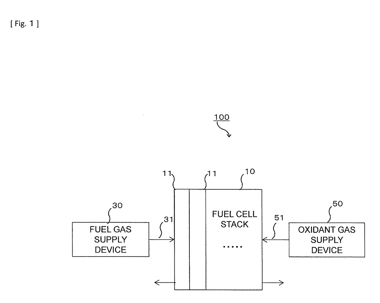
[0045]The configuration of a fuel cell system 100 according to Embodiment 1 is described with reference to FIG. 1. FIG. 1 is a functional block diagram schematically showing the configuration of the fuel cell system 100. The fuel cell system 100 includes a fuel cell stack 10, a fuel gas supply device 30, and an oxidant gas supply device 50.

[0046]The fuel cell stack 10 is a reactor configured to generate electric power by causing a hydrogen-containing fuel gas and an oxidant gas to electrochemically react with each other (hereinafter, such a reaction is referred to as a power-generating reaction). The fuel cell stack 10 includes a plurality of cells 11 that are stacked together.

[0047]The fuel gas supply device 30 is a device configured to supply the fuel gas to a channel of the fuel cell stack 10. The fuel gas supply device 30 is connected to the channel of the fuel cell stack 10 by a first passage 31, and the fuel gas is supplied to the fuel cell stack 10 through the first passage 3...

working example

[0093]An electrical resistance evaluation test, a hydrogen pump test, a power generation performance evaluation test, and a gas replacement cycle test were conducted on the cell 11 of a working example and a cell 111 of comparative example. First, methods of fabricating the cell 11 of the working example and the cell 111 of comparative example used in the above tests are described below. FIG. 4 is a sectional view schematically showing the cell 11 of the working example. FIG. 5 is a sectional view schematically showing the cell 111 of the comparative example.

[0094]The first electrically conductive material of the anode catalyst layer 19 of the MEA 12 of the cell 11 of the working example was prepared in the following manner. First, octylic acid titanium (2-ethylhexanoic acid titanium) and octylic acid tantalum (2-ethylhexanoic acid tantalum) were mixed such that the titanium-tantalum ratio was 10:1. The resulting mixture was dissolved in turpentine to prepare a precursor solution. T...


PUM

PropertyMeasurementUnit
Diameteraaaaaaaaaa
Diameteraaaaaaaaaa
Diameteraaaaaaaaaa

Abstract

A cell includes: a membrane electrode assembly; and a pair of separators. The membrane electrode assembly includes a polymer electrolyte membrane, an anode catalyst layer on a first main surface of the polymer electrolyte membrane, and a cathode catalyst layer on a second main surface. The anode catalyst layer contains a first catalyst material having activity against a hydrogen oxidation reaction and a first electrically conductive material whose electrical resistance under a hydrogen atmosphere and under an oxygen atmosphere are different from each other. The cathode catalyst layer contains a second catalyst material having activity against an oxygen reduction reaction and a second electrically conductive material different from the first electrically conductive material. An electrical resistance of the cell when the anode catalyst layer is under oxygen atmosphere is more than twice the electrical resistance of the cell when the anode catalyst layer is under hydrogen atmosphere.

Description

TECHNICAL FIELD[0001]The present invention relates to a cell, a fuel cell stack, a fuel cell system, and a membrane electrode assembly.BACKGROUND ART[0002]Conventionally, when the supply of a fuel gas to a polymer electrolyte fuel cell is stopped, the fuel gas remaining in a fuel gas channel may leak from the fuel gas channel, or may pass through a polymer electrolyte membrane. In such a case, air enters the fuel gas channel in place of the fuel gas. If the fuel cell is re-started in such a state, an oxygen reduction reaction occurs at the anode. This causes degradation of a catalyst used for the cathode. In order to avoid such catalyst degradation, at the time of re-starting the fuel cell, air remaining in the fuel gas channel is purged from the fuel gas channel by using an inert gas before the fuel gas is supplied to the fuel gas channel.[0003]However, this method requires, for example, a tank for storing the inert gas and a device for controlling the supply of the inert gas, caus...

Claims


Application Information

Patent Timeline
IPC IPC(8): H01M4/92B01J23/42B01J23/648H01M8/0206H01M8/1004H01M8/1018H01M4/86
CPCH01M4/92B01J23/42B01J23/648H01M8/0206H01M8/1004H01M8/1018H01M4/8657H01M2008/1095H01M8/10H01M4/86H01M4/90H01M8/02H01M4/8673H01M2004/8684Y02E60/50
Inventor SHINTANI, HARUHIKOKAKINUMA, KATSUYOSHIUCHIDA, MAKOTOWATANABE, MASAHIRO
Owner PANASONIC CORP
Why Eureka
Eureka Blog
Learn More