Method of producing inner spiral grooved tube and apparatus for producing inner spiral grooved tube

a technology of inner spiral and grooved tube, which is applied in the direction of tubular elements, lighting and heating apparatus, and stationary conduit assemblies, etc. it can solve the problems of difficult to remove the chip and difficult to manufacture by a groove rolling method, and achieve the effect of less shear stress, large twist and reduced diameter

Active Publication Date: 2018-06-07
MMA CO LTD
View PDF3 Cites 0 Cited by
  • Summary
  • Abstract
  • Description
  • Claims
  • Application Information

AI Technical Summary

Benefits of technology

[0032]According to the production method of the present invention, an inner spiral grooved tube is produced by combined processing in which twisting is applied and at the same time diameter reduction is performed by a drawing die. For this reason, shearing stress due to twisting and withdrawing stress due to drawing are concurrently applied to the tubular material; and twist can be imparted with a less shear stress compared to a case of a simple twisting processing. Accordingly, it is possible to impart a large twist to the tubular material before reaching the buckling stress of the tubular material.
[0033]Further, in the production method of the present invention, the tubular material is revolved by the revolving capstan between the first drawing die and the second drawing die which are different from each other in the drawing direction. Thereby, twisting can be applied twice in succession by making the twisting directions coincide with each other between the first twisting-drawing step in the first drawing die and the second twisting-drawing step in the second drawing die. Further, since there is no need to rotate the starting end and the terminal end of the tube route of the tubular material, it is not necessary to revolve the bobbins in the case where the unwinding bobbin, which supplies the tubular material on the starting end of the tube bath, and the winding bobbins, which recover the tubular material on the terminal end of the tube route, are provided. Therefore, it is easy to increase the rotation speed, and the line speed can be increased. In other words, according to the production method of the present invention, it is possible to mass-produce an inner spiral grooved tube to which a large twist angle is imparted.

Problems solved by technology

However, in a heat transfer tube made of an aluminum alloy, it is necessary to increase the bottom wall thickness in order to increase the pressure resistance, and it was difficult to manufacture by a groove rolling method.
Also, in groove rolling, aluminum chip is generated due to friction between the groove plug and the inner surface of the tube, and there is also a problem that it is difficult to remove the chip.

Method used


Image

  • Method of producing inner spiral grooved tube and apparatus for producing inner spiral grooved tube
  • Method of producing inner spiral grooved tube and apparatus for producing inner spiral grooved tube
  • Method of producing inner spiral grooved tube and apparatus for producing inner spiral grooved tube

Examples


Embodiment Construction

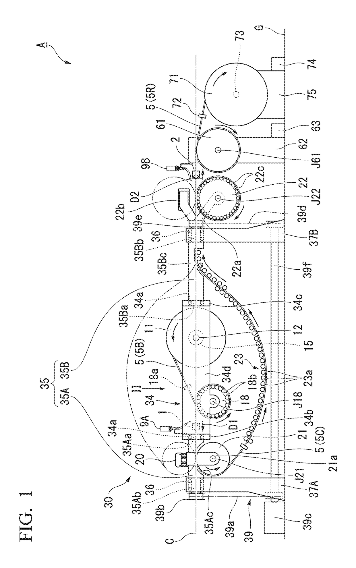
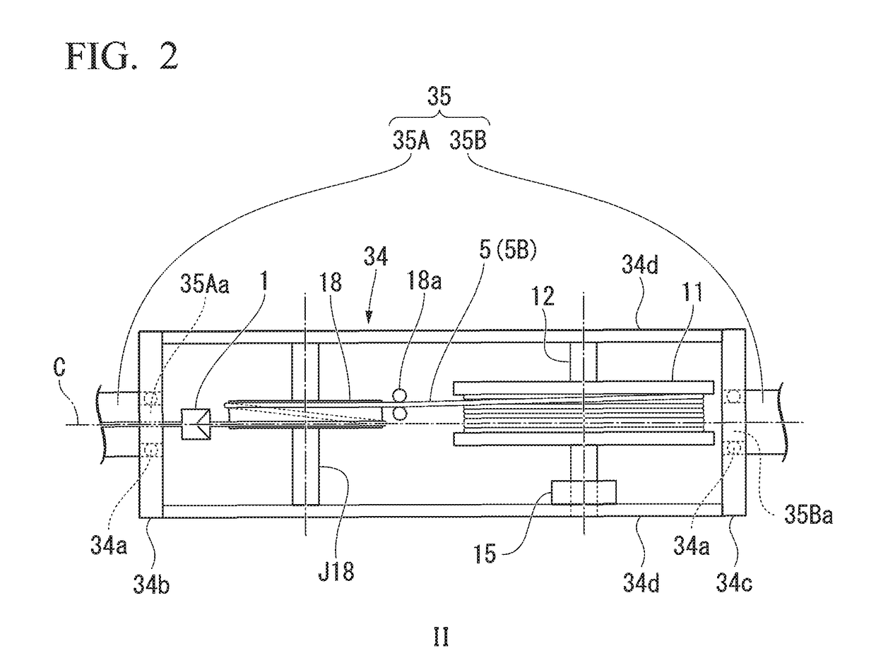
[0042]Hereinafter, embodiments of an apparatus for producing an inner spiral grooved tube according to the present invention and a method of producing an inner spiral grooved tube using the apparatus will be described with reference to the drawings. In the drawings used in the following description, for the sake of emphasizing the characteristic portion, there are cases where characteristic portions are enlarged for convenience and there are cases where the dimensional ratio of each component is not the same as the actual one. Also, for the same purpose, some parts that are not characteristic may be omitted for illustration.

[0043]In the present specification, the tubular material before being twisted is referred to as “linear grooved tube.” Also, the tubular material after being twisted is referred to as “inner spiral grooved tube.” Further, in the process from the linear grooved tube to the inner spiral grooved tube, an intermediate product having twisted about half as compared wit...


PUM

PropertyMeasurementUnit
twisting angleaaaaaaaaaa
outer diameteraaaaaaaaaa

Abstract

A method of producing an inner spiral grooved tube using a first drawing die using first and second drawing dice and a revolving flyer is provided. The method includes a first twisting-drawing step to form an intermediate twisted tube by reducing a diameter of a linear grooved tube, on an inner surface of which a plurality of straight grooves is formed along with a longitudinal direction, in conjunction with imparting twist to the linear grooved tube by passing the linear grooved tube through the first drawing die and then by revolving the liner grooved tube by wrapping the linear grooved tube around the revolving flyer; and a second twisting-drawing step to form an inner spiral grooved tube by reducing a diameter of the intermediate twisted tube by passing the intermediate twisted tube, which revolves with the revolving flyer, through the second drawing die in conjunction with imparting twist to the intermediate twisted tube.

Description

TECHNICAL FIELD[0001]The present invention relates to a method of producing an inner spiral grooved tube used for a heat transfer tube of a heat exchanger and an apparatus for producing the inner spiral grooved tube.[0002]Priority is claimed on Japanese Patent Application No. 2015-108307, filed May 28, 2015, the content of which is incorporated herein by reference.BACKGROUND ART[0003]In a fin-and-tube type heat exchanger such as an air conditioner or a water heater, a heat transfer tube for passing a coolant through the aluminum fin material is provided. In the heat transfer tube, an inner spiral grooved tube having a continuous spiral groove on the inner surface is mainly used for enhancing the heat exchange efficiency with the refrigerant.[0004]Conventionally, copper alloys have been mainly used for heat transfer tubes. However, due to demands for weight saving, cost reduction and improvement in recyclability, there is an increasing demand for the development of heat transfer tube...

Claims


Application Information

Patent Timeline
Patent Type & Authority Applications(United States)
IPC IPC(8): B21C1/22B21D53/06
CPCB21C1/22B21D53/06B21C37/207B21C1/04F28F1/40F28F21/084F28D1/0477
Inventor NAKAURA, YUSUKEHATERUMA, YUKI
Owner MMA CO LTD
Why Eureka
Try Eureka