Inverter Control Device
a control device and inverter technology, applied in the direction of dynamo-electric converter control, dynamo-electric gear control, dynamo-electric brake control, etc., can solve the problems of copper loss increase, and achieve the effect of reducing the overcurrent of the inverter and the motor
- Summary
- Abstract
- Description
- Claims
- Application Information
AI Technical Summary
Benefits of technology
Problems solved by technology
Method used
Image


Examples
first embodiment
[0018]FIG. 1 is a diagram illustrating a configuration of a motor drive device according to a
[0019]The motor drive device includes a motor 200, a position sensor 210, a current sensor 220, an inverter 100, and a motor control device 1.
[0020]The motor 200 is configured using an interior permanent magnet synchronous motor or the like to which a neutral point is not connected. A U-phase winding 201 wound around a stator of the motor 200 is connected to an output terminal of a U-phase full bridge inverter 110. A V-phase winding 202 wound around the stator of the motor 200 is connected to an output terminal of a V-phase full bridge inverter 111. A W-phase winding 202 wound around the stator of the motor 200 is connected to an output terminal of a W-phase full bridge inverter 112.
[0021]The motor 200 according to the present embodiment independently controls each current flowing in the U-phase winding 201, the V-phase winding 202, and the W-phase winding 203 since the neutral point is not ...
second embodiment
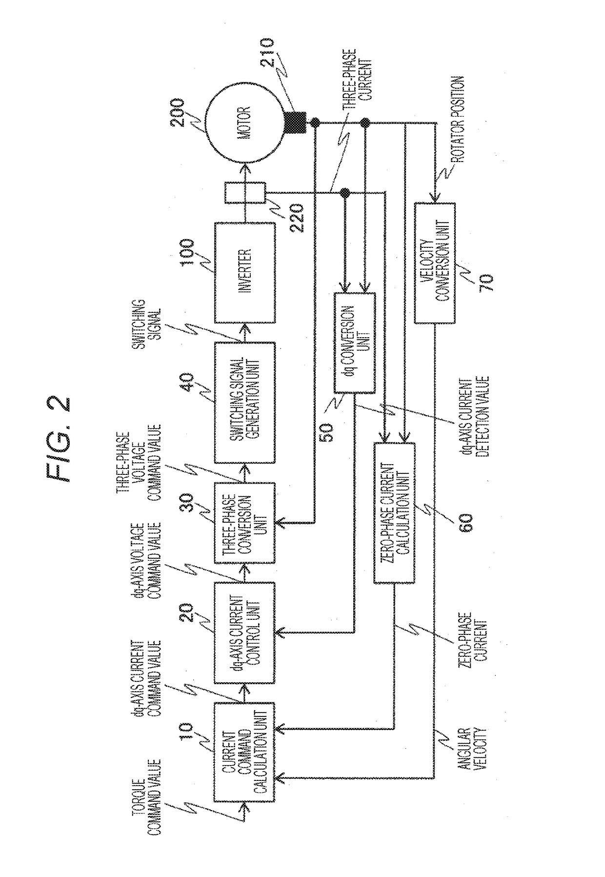
[0044]FIG. 6 is a block diagram illustrating a A configuration of FIG. 6 is a configuration obtained by adding a current command correction unit 300 to FIG. 2. In FIG. 6, the current command calculation unit 10 calculates the d-axis current command values id* and iq* that do not exceed the predetermined current imax without considering the zero-phase current i0 according to the input torque command value T*. The dq-axis current command values id* and iq* and the zero-phase current i0are input to the current command correction unit 300, and the dq-axis current command values id* and iq* are corrected so as to satisfy the condition of Formula (1). At this time, it is possible to correct only the q-axis current command value iq* or only the d-axis current command value id*, or both the d-axis current command value id* and the q-axis current command value iq*.
third embodiment
[0045]FIG. 7 is a block diagram, illustrating a A configuration of FIG. 7 is a configuration obtained by adding a torque command correction unit 400 to FIG. 2. In FIG. 7, the torque command value T* and the zero-phase current i0 are input to the torque command correction unit 400, the torque command value T* is corrected using a table set in advance, and the corrected torque command value is output. By the above-described correction, the torque command value T*, which enables the sum of the dq-axis current command values id* and iq* and the zero-phase current iq* to be equal to or lower than the predetermined current, is generated.
PUM
 Abstract
Description
Claims
Application Information
 - R&D
- Intellectual Property
- Life Sciences
- Materials
- Tech Scout
- Unparalleled Data Quality
- Higher Quality Content
- 60% Fewer Hallucinations
Browse by: Latest US Patents, China's latest patents, Technical Efficacy Thesaurus, Application Domain, Technology Topic, Popular Technical Reports.
© 2025 PatSnap. All rights reserved.Legal|Privacy policy|Modern Slavery Act Transparency Statement|Sitemap|About US| Contact US: help@patsnap.com