Water hammer-proof air valve and water hammer-proof exhaust method for in-use pipeline

Active Publication Date: 2018-05-31
ZHUZHOU SOUTHERN VALVE
View PDF6 Cites 4 Cited by
  • Summary
  • Abstract
  • Description
  • Claims
  • Application Information

AI Technical Summary

Benefits of technology

The present invention provides a water hammer-proof air valve and a water hammer-proof exhaust method for a pipeline in-use. The technical effects of the invention include preventing valve-closing water hammer, avoiding blowing-block during a high-speed exhaust, and ensuring complete exhaust. The invention also includes a sealing disc and a shield to prevent contamination from entering the valve body. The high-speed exhaust throttling device designed at the exhaust outlet can input throttling under a set exhaust amount and exhaust pressure difference, which only throttles the high-speed exhaust that may cause water hammer of cavity collapsing, and will not have any effect on high-speed air intake and trace exhaust. The invention also integrates a trace exhaust device inside the high-speed intake and exhaust device, which can realize an exhaust whenever air presents, an exhaust under full pressure, a complete exhaust, a function of exhaust without drain, and an improvement of conveyance efficiency of the pipeline. The invention also includes a water pressure relief valve that opens when the pipeline pressure drops to nearly a negative pressure, which prevents pipeline collapsing caused by the negative pressure.

Problems solved by technology

In a long distance water pipeline, air accumulated in the pipeline will reduce filling efficiency of the pipeline, or even make filling of the pipeline impossible to be successfully completed.
However, its closing member can be easily seized by high-speed airflow during a high-speed exhaust process, and then suddenly blocks the exhaust vent, which leads to a blowing-block phenomenon or an air-block phenomenon.
It will also cause the generation of a valve-closing water hammer of the air valve when blowing-block occurs.
It cannot inhibit a cavity-closing water hammer and the valve-closing water hammer.

Method used


Image

  • Water hammer-proof air valve and water hammer-proof exhaust method for in-use pipeline
  • Water hammer-proof air valve and water hammer-proof exhaust method for in-use pipeline
  • Water hammer-proof air valve and water hammer-proof exhaust method for in-use pipeline

Examples


Embodiment Construction

[0027]Embodiments of the present invention described in detail below in combination with the accompanying drawings, but the present invention may be implemented by a plurality of different ways that are defined and covered.

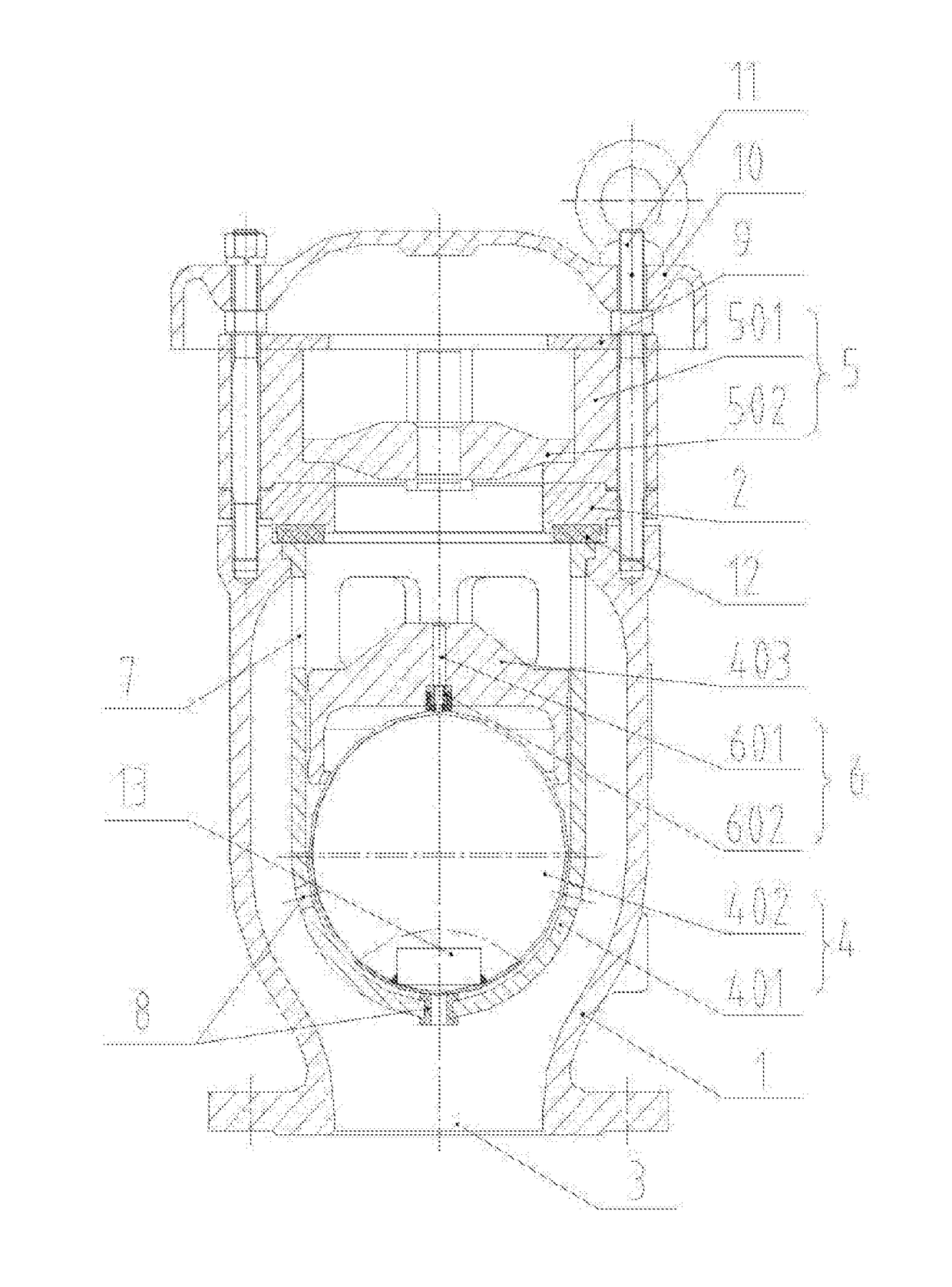
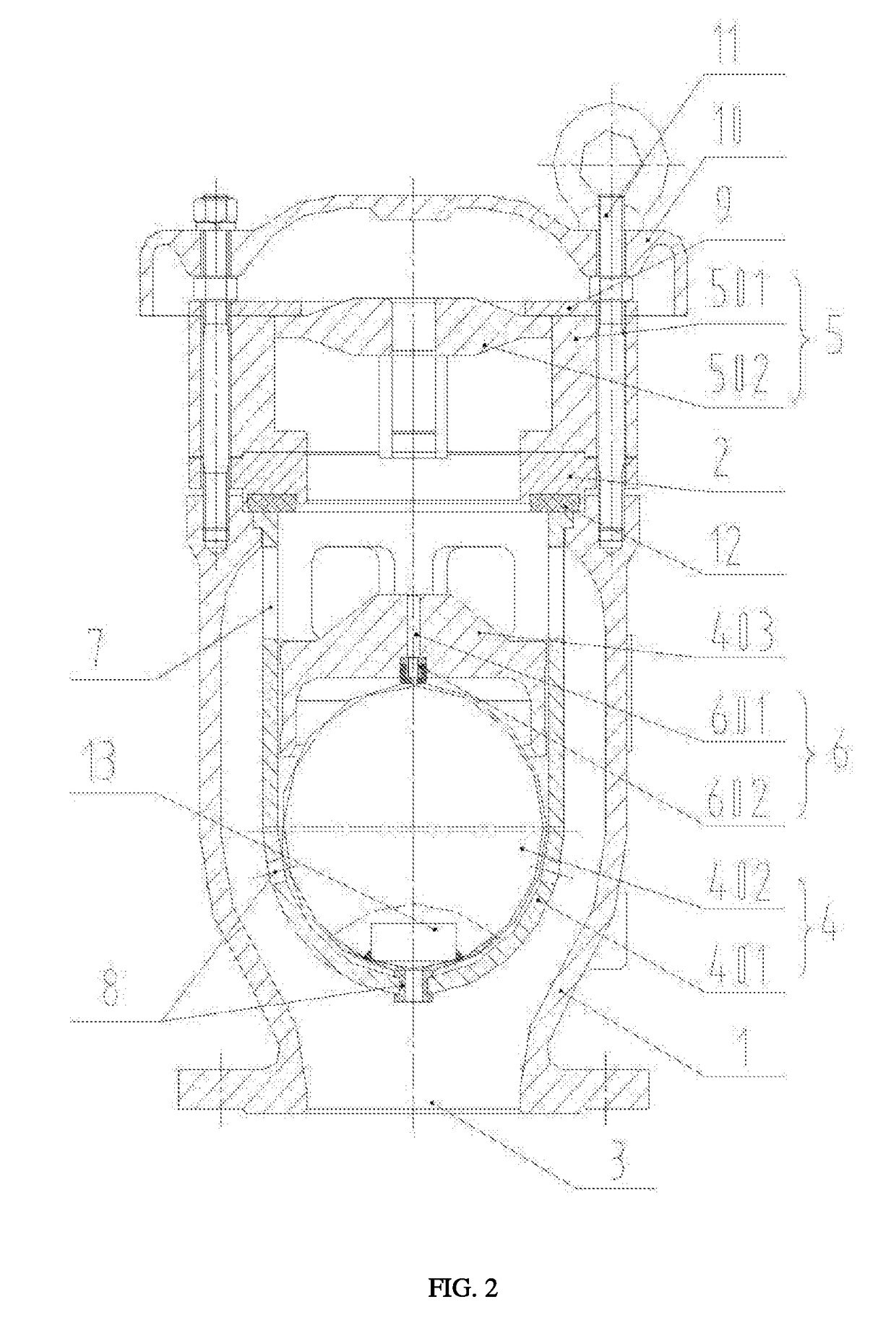
[0028]FIG. 1 is a structural representation of a trace exhaust valve seat and a throttle disc both not in a working state of a water hammer-proof air valve according to a preferred embodiment of the present invention. FIG. 2 is a structural representation of a trace exhaust valve seat not in a working state and a throttle disc in a working state of a water hammer-proof air valve according to a preferred embodiment of the present invention. FIG. 3 is a structural representation of a trace exhaust valve seat in a working state and a throttle disc not in a working state of a water hammer-proof air valve according to a preferred embodiment of the present invention. FIG. 4 is structural representation of a trace exhaust valve seat in a working and entering a trace exha...


PUM


Abstract

A water hammer-proof air valve that has a valve body and a bonnet, that are fixedly connected, a valve opening is provided on the valve body, and a high-speed intake and exhaust device is provided in an inner cavity of the valve body. A bonnet opening is provided on the bonnet, an output end of the high-speed intake and exhaust device penetrates the bonnet opening and is communicated with a high-speed exhaust throttling device for limiting an exhaust amount of gas of the high-speed intake and exhaust device, an output end of the high-speed exhaust throttling device is communicated with an outside air, and a trace exhaust device for discharging the gas separated out from the pipeline to the outside through the high-speed exhaust throttling device after the high-speed intake and exhaust device closes the valve is further provided in the high-speed intake and exhaust device.

Description

TECHNICAL FIELD[0001]The present invention relates to the field of a water pipeline valve, and more specifically, to an overhead throttle exhaust type water hammer-proof air valve. In addition, the present invention relates to a water hammer-proof exhaust method for a pipeline in-use.BACKGROUND[0002]In a long distance water pipeline, air accumulated in the pipeline will reduce filling efficiency of the pipeline, or even make filling of the pipeline impossible to be successfully completed. Therefore, a high-speed intake and exhaust valve (air valve) is required to remove air in the pipe while filling the pipeline with water.[0003]And the current high-speed intake and exhaust valve (air valve) mainly uses:[0004](i) Direct motion type or floating ball operation type high-speed intake and exhaust valve (air valve), will automatically exhaust a large amount of air when filling the blank pipe with water or suction a large amount of air when emptying the pipeline system; and under a condit...

Claims


Application Information

Patent Timeline
IPC IPC(8): F16K47/02F16K1/14F16K47/08F16L55/07
CPCF16K47/02F16K1/14F16K47/08F16L55/07F16K24/046F16L55/055F16K17/366F16K24/044F16K31/22F16K21/18Y10T137/3099F16K47/023F16K33/00Y10T137/7436
Inventor HUANG, JINGGUI, XINCHUNTANG, JINPENGYIN, JIANGUOXU, QIUHONGXIE, AIHUATANG, AIHUA
Owner ZHUZHOU SOUTHERN VALVE
Why Eureka
Try Eureka