
Time of flight photosensor

a photosensor and time-of-flight technology, applied in the field of photosensors, can solve the problems of large computer processing power, difficult to create 3d images using small devices, complex techniques,

Active Publication Date: 2018-04-26
OMNIVISION TECH INC
View PDF0 Cites 13 Cited by
  • Summary
  • Abstract
  • Description
  • Claims
  • Application Information

AI Technical Summary

Benefits of technology

The patent text describes a time of flight photosensor apparatus and method for acquiring 3D images in real-time applications. The technical effects of this invention include reducing errors in time of flight measurements, improving sensitivity to noise, and addressing challenges in detecting reflected photons. The invention also provides a method for accurately determining the round trip distance to an object using time of flight. These technical effects are important for creating high-quality 3D images in real-time applications.

Problems solved by technology

One disadvantage with this triangulation technique is that it is difficult to create 3D images using small devices because there must be a minimum separation distance between each camera in order to create the three dimensional images.
In addition, this technique is complex and therefore requires significant computer processing power in order to create the 3D images in real time.
A continuing challenge with the acquisition of 3D images is that the required processing must occur very quickly in order for the 3D image acquisition system to resolve time differences on the order of, for example, 0.1 ns for real time applications.
With such short response times required for real time applications, sensitivity to noise, jitter, clock signals, heat, etc., in systems that acquire 3D images present increasing challenges as required response times are reduced.
Further challenges are also presented when the light that is reflected back from an object is not detected by the sensor of the 3D image acquisition system.

Method used


Image

  • Time of flight photosensor
  • Time of flight photosensor
  • Time of flight photosensor

Examples


Embodiment Construction

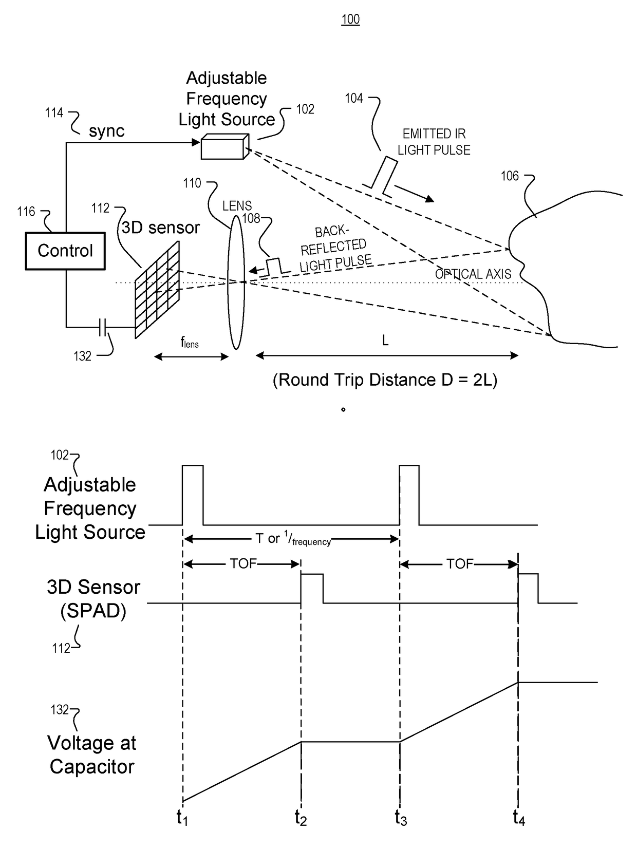
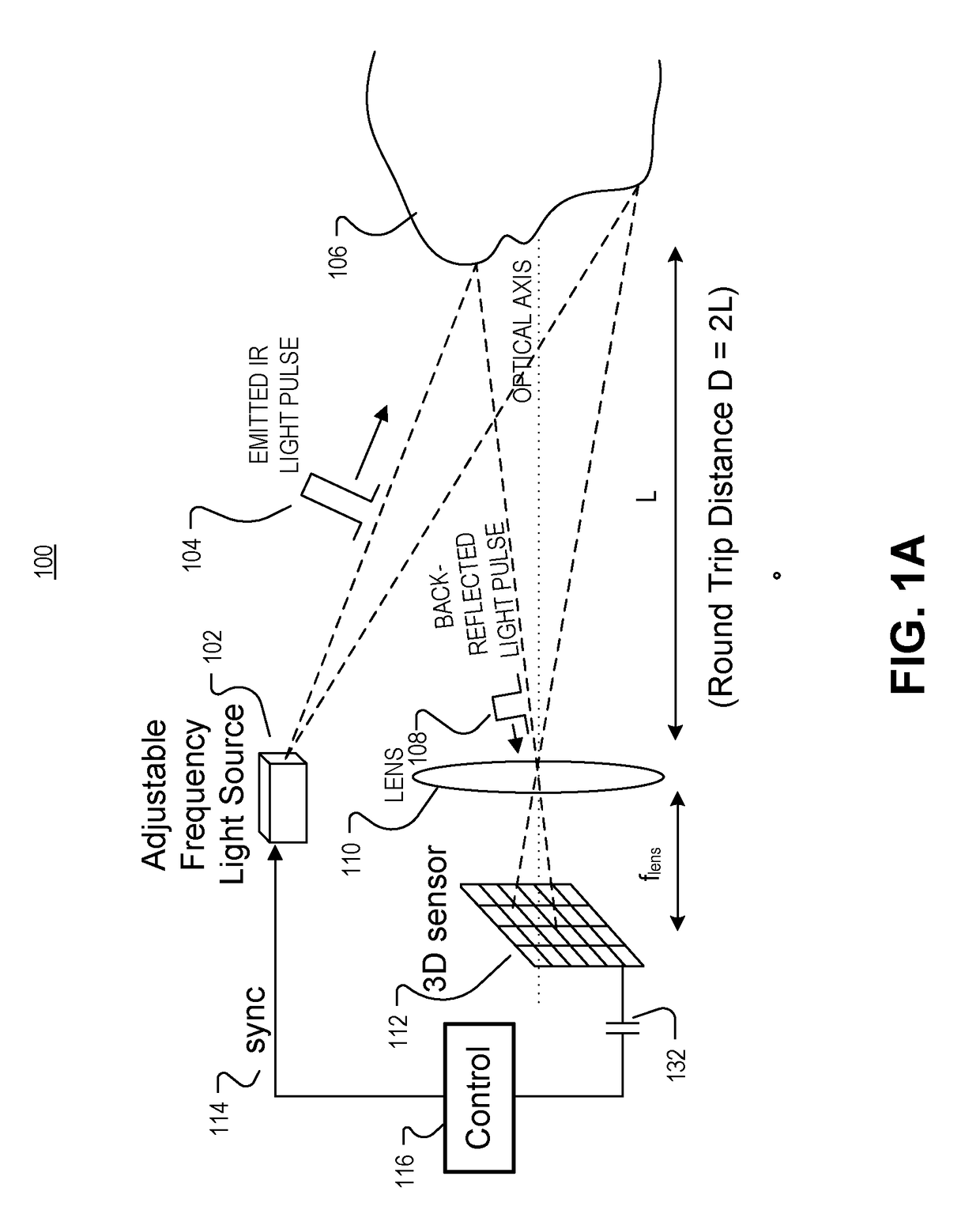
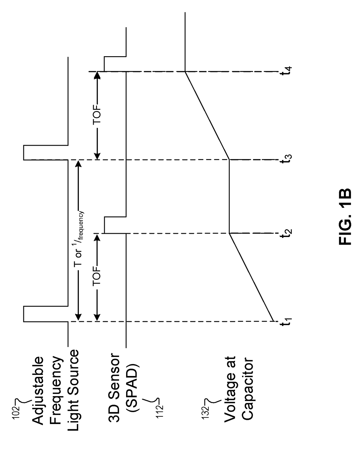
[0015]Examples of an apparatus and method for time of flight photosensors are described herein. In the following description, numerous specific details are set forth to provide a thorough understanding of the examples. One skilled in the relevant art will recognize, however, that the techniques described herein can be practiced without one or more of the specific details, or with other methods, components, materials, etc. In other instances, well-known structures, materials, or operations are not shown or described in detail to avoid obscuring certain aspects.

[0016]Reference throughout this specification to “one example” or “one embodiment” means that a particular feature, structure, or characteristic described in connection with the example is included in at least one example of the present invention. Thus, the appearances of the phrases “in one example” or “in one embodiment” in various places throughout this specification are not necessarily all referring to the same example. Fur...


PUM


Abstract

A time of flight pixel cell includes a photosensor to sense photons reflected from an object and pixel support circuitry. The pixel support circuitry includes charging control logic coupled to the photosensor to detect when the photosensor senses the photons reflected from the object. The pixel support circuitry also includes a controllable current source coupled to provide a charge current in response to a time of flight signal coupled to be received from the charging control logic. A capacitor is coupled to receive the charge current from the controllable current source in response to the time of flight signal, and voltage on the capacitor is representative of a round trip distance to the object. A counter circuit is coupled to the photosensor to count a number of the photons reflected from the object and received by the photosensor.

Description

TECHNICAL FIELD[0001]This disclosure relates generally to photosensors, and more specifically relates to reducing error in time of flight measurements.BACKGROUND INFORMATION[0002]Interest in three dimensional (3D) cameras is increasing as the popularity of 3D applications such as imaging, movies, games, computers, user interfaces, and the like continues to grow. A typical passive way to create 3D images is to use multiple cameras to capture stereo or multiple images. Using the stereo images, objects in the images can be triangulated to create the 3D image. One disadvantage with this triangulation technique is that it is difficult to create 3D images using small devices because there must be a minimum separation distance between each camera in order to create the three dimensional images. In addition, this technique is complex and therefore requires significant computer processing power in order to create the 3D images in real time.[0003]For applications that require the acquisition ...

Claims


Application Information

Patent Timeline
IPC IPC(8): H04N13/00H04N13/02H04N13/122
CPCH04N13/0253H04N13/0018G01J11/00H04N13/122G01B11/24G01S17/10G01S7/4863G01S7/4865G01S7/4868H04N13/254G01S3/00
Inventor BULTEEL, OLIVIERWANG, RUIYANG, ZHENG
Owner OMNIVISION TECH INC
Learn More