
Four-wheel drive vehicle and control apparatus for four-wheel drive vehicle

a control apparatus and vehicle technology, applied in the direction of mechanical actuated clutches, interlocking clutches, vehicle sub-unit features, etc., can solve the problems of inability to accurately control the friction clutch, error in the current output of the control apparatus to the friction clutch, etc., to achieve the effect of increasing the accuracy of the current output of the control apparatus in order to control the friction clutch

Active Publication Date: 2018-04-12
JTEKT CORP
View PDF0 Cites 9 Cited by
  • Summary
  • Abstract
  • Description
  • Claims
  • Application Information

AI Technical Summary

Benefits of technology

[0007]It is one object of the present invention to provide a four-wheel drive vehicle including a dog clutch and a friction clutch provided such that a driving shaft is interposed therebetween in a driving force transmission path to auxiliary driving wheels, and a control apparatus configured to control the dog clutch and the friction clutch, in which the accuracy of a current to be output from the control apparatus in order to control the friction clutch can be increased.
[0017]According to the four-wheel drive vehicle of the aspect described above, it is possible to increase the accuracy of the current to be output from the control apparatus in order to control the friction clutch.

Problems solved by technology

For example, when a sensor unit configured to detect a current and an amplifier circuit configured to amplify a signal output from the sensor unit have an offset in their characteristics due to changes over time or temperature, however, an error occurs in the current output from the control apparatus to the friction clutch even when the feedback control is performed.
As a result, the friction clutch cannot be controlled accurately.

Method used


Image

  • Four-wheel drive vehicle and control apparatus for four-wheel drive vehicle
  • Four-wheel drive vehicle and control apparatus for four-wheel drive vehicle
  • Four-wheel drive vehicle and control apparatus for four-wheel drive vehicle

Examples


first embodiment

[0030]the present invention is described with reference to FIG. 1 to FIG. 7.

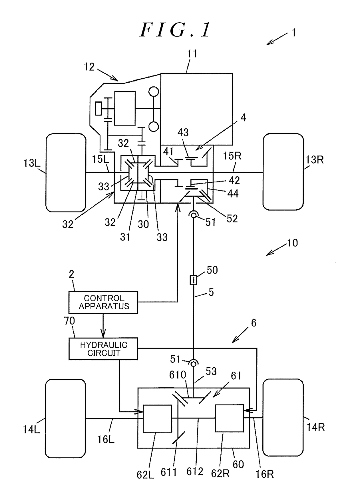
[0031]FIG. 1 is a structural diagram illustrating the schematic structure of a four-wheel drive vehicle according to the first embodiment of the present invention.

[0032]A four-wheel drive vehicle 1 includes an engine 11 serving as a drive source configured to generate a driving force for traveling, a transmission 12 configured to vary the speed of rotation output from the engine 11, front wheels 13R and 13L serving as a pair of right and left main driving wheels, rear wheels 14R and 14L serving as a pair of right and left auxiliary driving wheels, a driving force transmission system 10 capable of transmitting the driving force of the engine 11, which is obtained through the speed variation performed by the transmission 12, to the front wheels 13R and 13L and the rear wheels 14R and 14L, and a control apparatus 2. In this embodiment, the suffixes “R” and “L” of the reference symbols are used to present “right...


PUM


Abstract

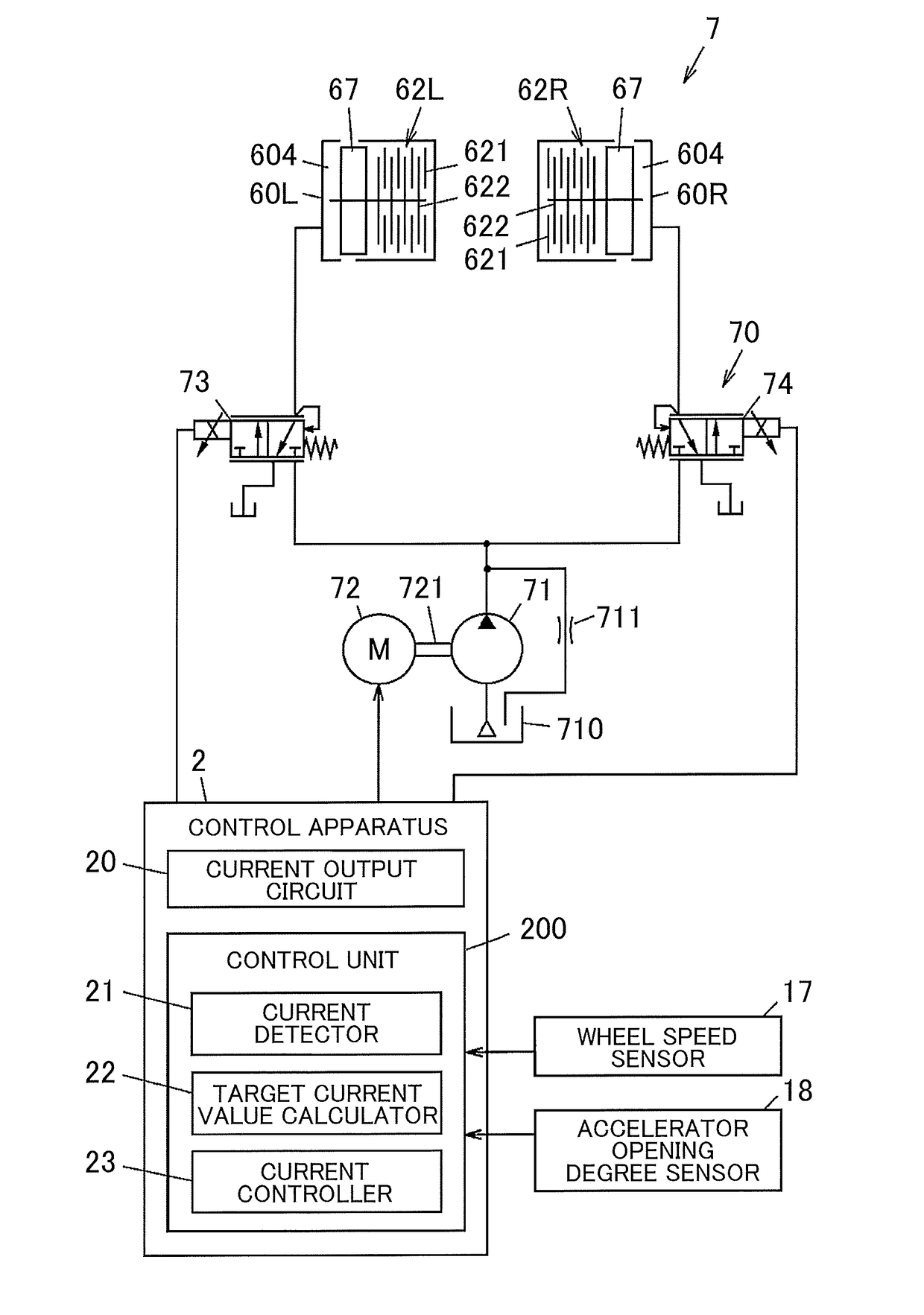
A control apparatus for a four-wheel drive vehicle includes a current detector configured to output a detection signal in accordance with the magnitude of an actual control current, a target current value calculator configured to calculate a target current value that is a target value of the control current, and a current controller configured to control a current output circuit to output the control current having the target current value calculated by the target current value calculator based on a result of detection performed by the current detector. When the four-wheel drive vehicle is in a two-wheel drive mode in which first and second friction clutches are released, the current controller performs zero-point adjustment for adjusting a zero point of the control current to be output from the current output circuit.

Description

INCORPORATION BY REFERENCE[0001]The disclosure of Japanese Patent Application No. 2016-200258 filed on Oct. 11, 2016 including the specification, drawings and abstract, incorporated herein by reference in its entirety.BACKGROUND OF THE INVENTION1. Field of the Invention[0002]The present invention relates to a four-wheel drive vehicle including main driving wheels to which a driving force of a drive source is constantly transmitted, and auxiliary driving wheels to which the driving force is transmitted in a disconnectable manner. The present invention also relates to a control apparatus for the four-wheel drive vehicle.2. Description of the Related Art[0003]Hitherto, there is known a four-wheel drive vehicle including main driving wheels to which a driving force of a drive source is constantly transmitted, a driving shaft configured to transmit the driving force in a fore-and-aft direction of the vehicle, auxiliary driving wheels to which the driving force of the drive source is tran...

Claims


Application Information

Patent Timeline
IPC IPC(8): B60K23/08B60K17/02B60K17/348F16D11/14F16D48/06F16D25/061F16D27/118F16D13/52
CPCB60K23/08B60K17/02B60K17/348F16D11/14F16D48/06F16D25/061F16D27/118F16D13/52F16D2500/10431F16D2500/1045F16D2500/10462B60K17/354B60Y2400/424B60K2023/0866B60K17/344B60K17/3515B60K23/0808B60K2023/0858B60Y2400/421F16D25/10F16D27/115F16D2023/123F16D2500/3022F16D2500/70406F16D2500/70418F16D2500/1026F16D2500/1022F16D2500/1023F16D25/082F16D25/0638
Inventor NOZU, TOMOHIRONAGAYAMA, GONIIMI, SHOTAROKAKITA, AKIYOSHISARAI, KOTARO
Owner JTEKT CORP
Learn More