
Feedback compensated oscillator

a technology of oscillator and compensation, applied in the direction of oscillator, pulse generator, pulse technique, etc., can solve the problems of variation in output frequency, loss of output frequency, and inability to achieve off-chip crystal reference,

Active Publication Date: 2018-03-29
MACRONIX INT CO LTD
View PDF11 Cites 16 Cited by
  • Summary
  • Abstract
  • Description
  • Claims
  • Application Information

AI Technical Summary

Benefits of technology

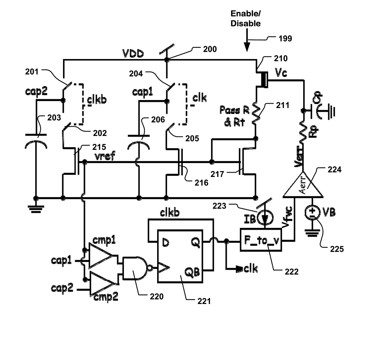
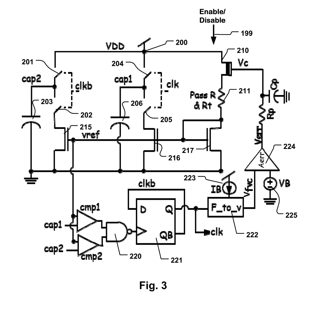
The patent describes a clock circuit and a method for manufacturing it. The clock circuit includes an oscillator that produces an oscillator output signal, which can be used as a clock signal or a frequency reference on an integrated circuit. The oscillator includes a RC network with a voltage-controlled element and a tunable element. The feedback circuit generates a control signal for the voltage-controlled element and includes an adjustable reference circuit and a loop amplifier. The clock circuit can operate at lower frequencies of 24 MHz and lower, and at frequencies critical for current high-speed circuits, up to 25 GHz. The loop amplifier includes an error amplifier and a low pass filter, and the voltage-controlled element can be a depletion mode NMOS transistor or a varactor. The first and second static parameters can be stored in nonvolatile memory on the same integrated circuit as the clock circuit. The method includes forming the oscillator, trimming the adjustable resistor and reference circuit, setting the first static parameter, connecting the feedback circuit to the oscillator output signal, and setting the second static parameter. The technical effects of this patent include providing a clock circuit that can operate at lower frequencies and higher frequencies, and a method for manufacturing it that includes trimming and adjusting static parameters.

Problems solved by technology

In other embodiments, an off-chip crystal reference may not be practical.
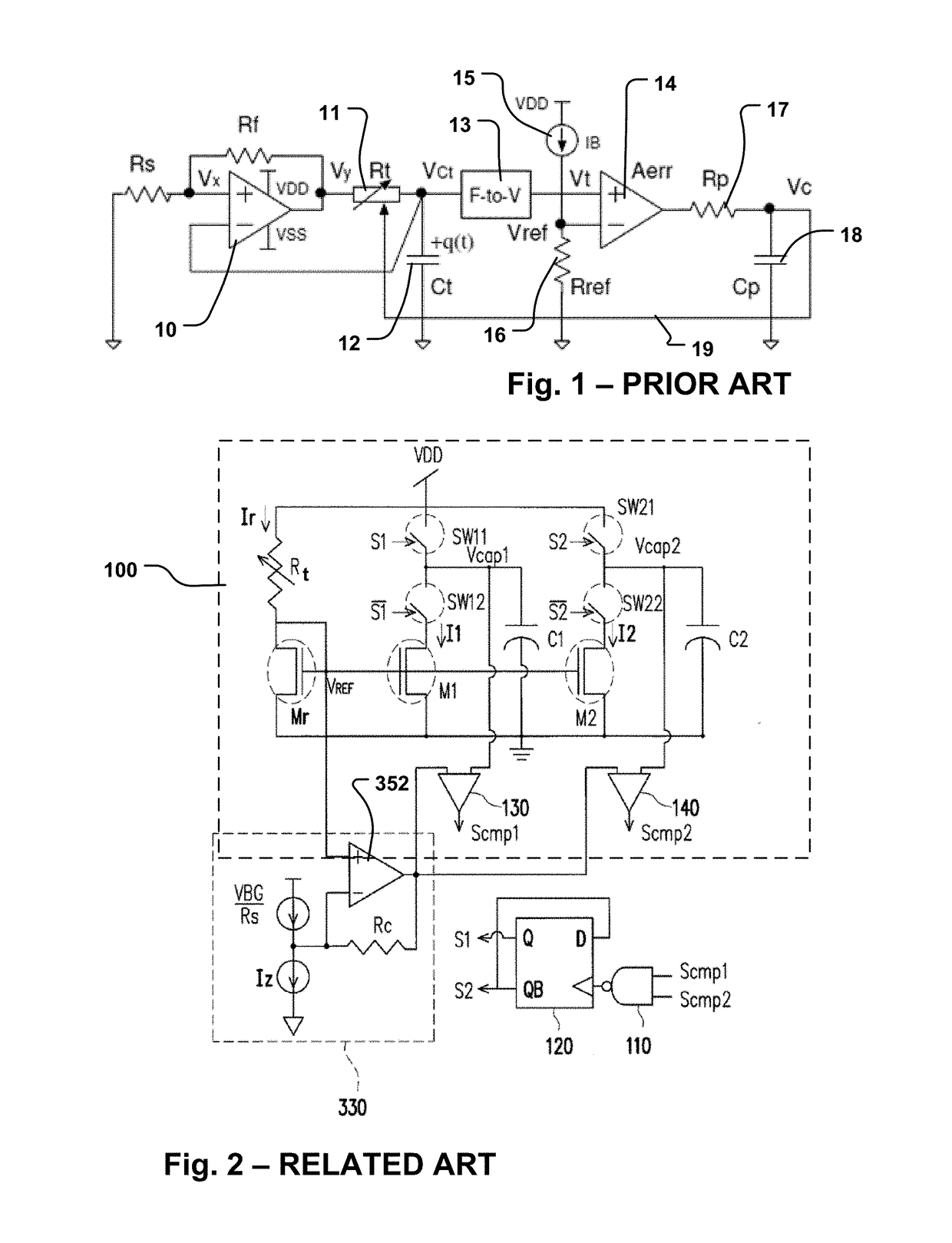
However if the loop parameters, like VREF (which is equal to IB*RREF in this configuration), the gain of the loop error amplifier Aerr and the coefficient of the frequency-to-voltage converter F-to-V may not be ideal.
Any non-ideality from these parameters would result in variations in the output frequency.
For example, the drift of Rref due to change in temperature can cause undesirable changes in the oscillating frequency.
This constraint may not be practical, particularly in single powered systems.
At higher frequencies, greater than 10 MHz for example shown in Sato et al., the prior art clock circuits may not be able to maintain stable clock frequencies with the existing feedback techniques.

Method used


Image

  • Feedback compensated oscillator
  • Feedback compensated oscillator
  • Feedback compensated oscillator

Examples


Embodiment Construction

[0038]A detailed description of embodiments of the technology is provided with reference to the FIGS. 2-14.

[0039]FIG. 2 shows related technology, It is a copy of FIG. 4 from U.S. Patent Application Publication No. US 2015 / 0333736, entitled Method And Circuit For Temperature Dependence Reduction Of A RC Clock Circuit, published Nov. 19, 2015, which is commonly owned by the present applicant now, and was commonly owned by the present applicant at the time the present application is being filed, and at the time of invention. U.S. Patent Application Publication No. US 2015 / 0333736 is incorporated by reference as if fully set forth herein.

[0040]FIG. 2 is a schematic diagram illustrating an RC relaxation oscillator comprising a combination of an RC clock circuit 100 and a temperature dependence reduction circuit 330.

[0041]In the RC clock circuit 100, a resistance / capacitance network includes resistor Rt, capacitors C1 and C2, and switches SW11, SW12, SW21 and SW22. Transistors Mr, M1 and ...


PUM


Abstract

An oscillator produces an oscillator output signal usable as a clock signal, otherwise as a frequency reference on an integrated circuit. The oscillator includes an RC network with a voltage-controlled element, such as a voltage-controlled resistor, voltage-controlled capacitor or a combination including a voltage-controlled resistor and voltage-controlled capacitor. Also, a tunable element having an adjustable resistance determined by a first static parameter is included in the RC network. The oscillator also includes a feedback circuit which can include a frequency-to-voltage converter. The feedback circuit generates a control signal for the voltage-controlled element. The feedback circuit includes a feedback reference circuit having a reference output determined by a second static parameter, and a loop amplifier responsive to the reference output and the oscillator output signal.

Description

BACKGROUNDTechnological Field[0001]The present technology relates to feedback-stabilized oscillators, including such oscillators formed on an integrated circuit and providing a stable operating frequency for circuitry on the integrated circuit.Description of Related Art[0002]In many integrated circuit based systems, it is important to provide an oscillator output signal with a stable operating frequency. In some systems, external clock reference circuits, such as crystal oscillators are used to stabilize an oscillator producing an on-chip clock. In other embodiments, an off-chip crystal reference may not be practical. So technology is being developed to provide stabilized on-chip oscillators.[0003]For example, FIG. 1 shows a prior art model of an RC relaxation oscillator architecture that is reported in Sato, et al., “Frequency-to-Voltage Converter for Temperature Compensation of CMOS RC Relaxation Oscillator,” Asia Pacific Conference on Circuits and Systems (APCCAS), 2014 IEEE, 17-...

Claims


Application Information

Patent Timeline
IPC IPC(8): H03B5/24H03K4/501
CPCH03K4/501H03B5/24H03B5/26H03K3/011H03K3/0231
Inventor WU, HSIEN-HUNG
Owner MACRONIX INT CO LTD
Learn More