
Method for reducing forces (hot fill/re-fill)

Inactive Publication Date: 2018-03-22
AMMINEX EMISSIONS TECH
View PDF0 Cites 0 Cited by
  • Summary
  • Abstract
  • Description
  • Claims
  • Application Information

AI Technical Summary

Benefits of technology

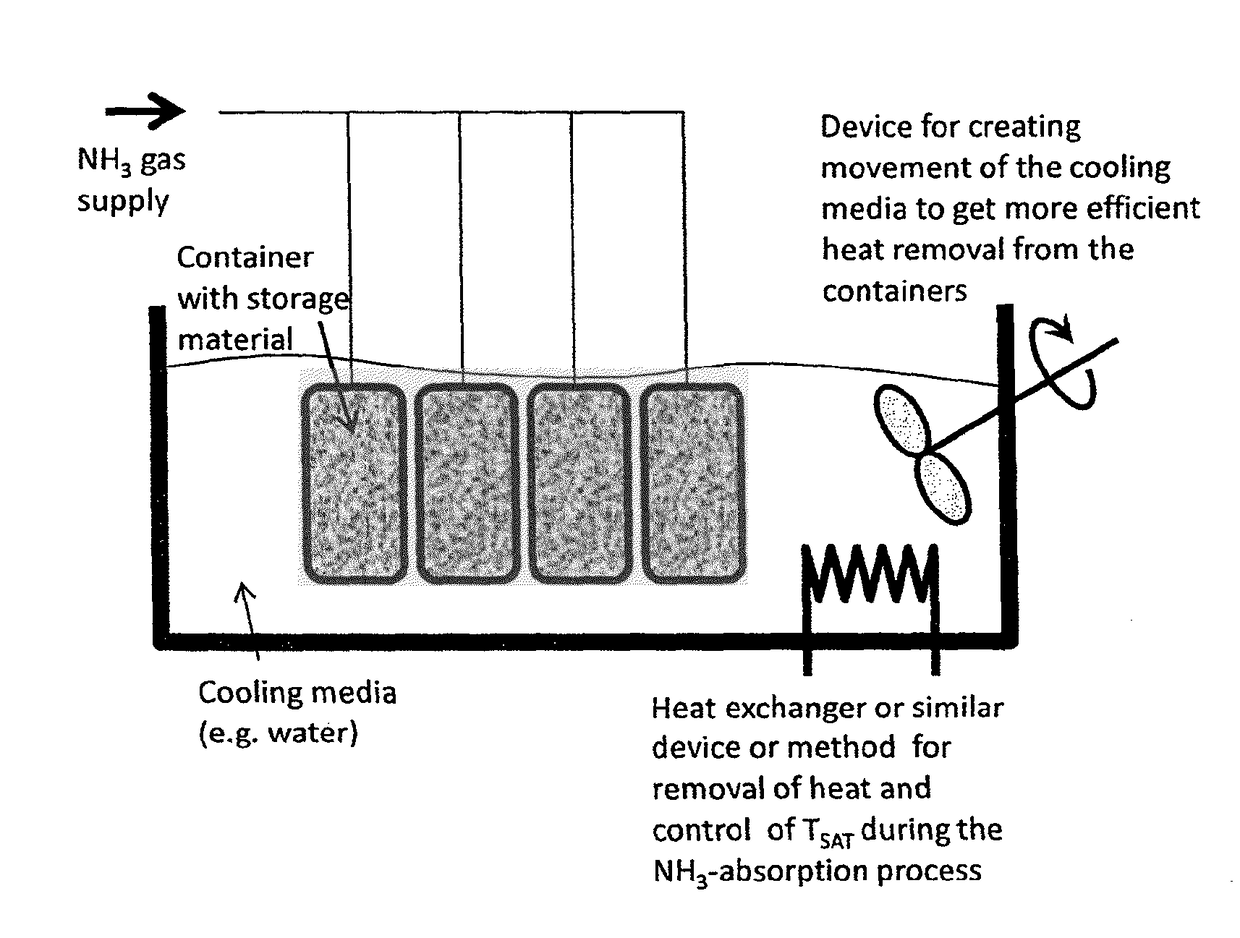
The present invention provides a method for producing a durable and cost-effective ammonia storage material with attractive properties. The method involves reducing expansion forces of the ammonia storage material during saturation or resaturation with ammonia, which prevents deformation of the metal container that encapsulates the material. The method also allows for the simplification of the production process for in-situ saturated cartridges, where not-yet-saturated storage material is placed inside the cartridge prior to saturation and is saturated for the first time inside the (metal) cartridge shell.

Problems solved by technology

For most end-user applications, and in particular in automotive applications, the storage of ammonia as pure, pressurized anhydrous ammonia in a pressure vessel is too hazardous.
When such cartridges holding metal ammine complexes are used on a vehicle, they gradually become depleted of ammonia and degassed salt material remain in the metal cartridge.
One-time-use of such a unit is too expensive and not a sustainable solution.
Metal ammine complexes have been studied in the past years and it has turned out to be a challenging class of material.
Saturation or resaturation of depleted ammonia storage material in a metal container cannot be done practically on the vehicle since it takes much more than just a few minutes to resaturate (removal of absorption heat by cooling may take several hours) and it requires anhydrous ammonia available next to the vehicle.
This expansion, which is also mentioned in WO 2010 / 025947 A1, leads to high mechanical forces which in turn may deform the metal wall of the cartridges or damage an internal structure for improving the heat transfer.
Over several refilling / degassing cycles the shape or performance of the cartridge may degrade to a level where the cartridge will become unusable and the deformation will lead to no longer fitting in the volume or installation space intended for the cartridge.
Thick-walled cartridges become both expensive and heavy while a significant reduction in the targeted storage density (reduced salt loading per unit volume) makes the cartridge industrially unattractive as an ammonia carrying unit because of poor utilization of the overall volume on the vehicle.
Unless all three are proven for an ammonia storage product, it is difficult to find a relevant place on the market that allows capturing the huge environmental benefits of being able to dose ammonia gas directly for optimal SCR NOx reduction.

Method used


Image

  • Method for reducing forces (hot fill/re-fill)
  • Method for reducing forces (hot fill/re-fill)
  • Method for reducing forces (hot fill/re-fill)

Examples


example 2

Metal Wall Thickness Based on a Fixed Saturation, Temperature, and Storage-Material Density

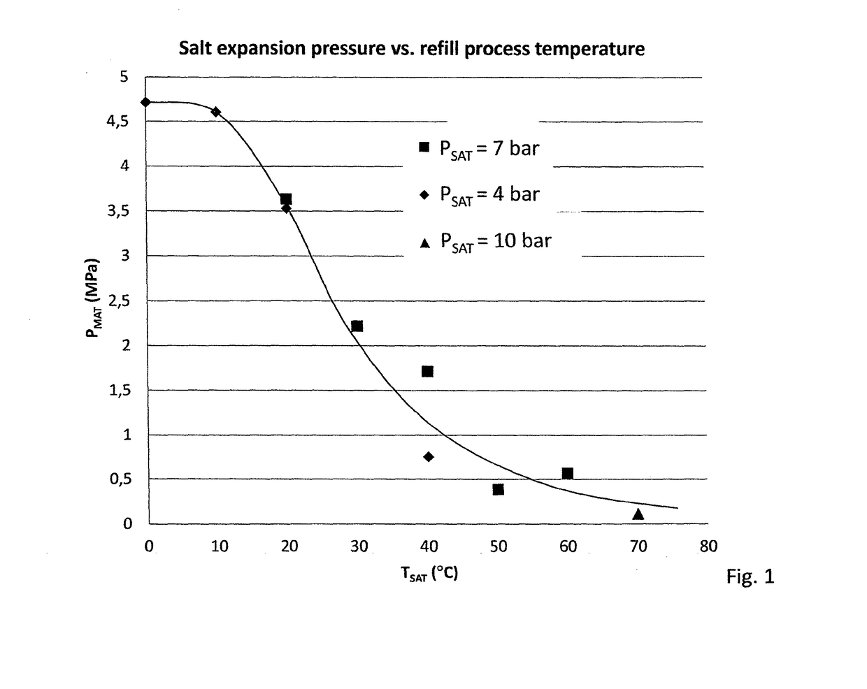
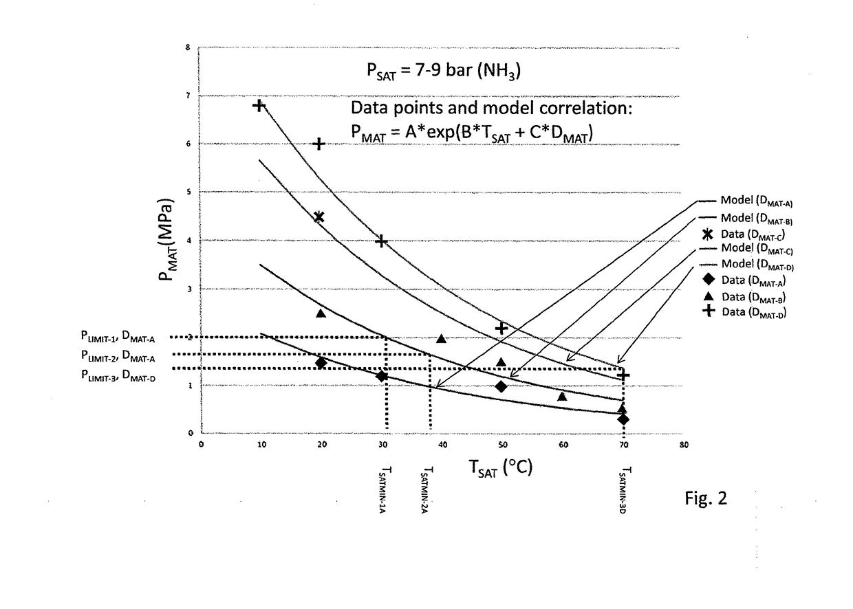
[0086]A refill process has been established to refill cartridges at a temperature of 20° C. The ammonia storage material density given is 1175 g / cm3, which gives a material pressure PMAT=3.2 MPa. The cartridge is cylindrical, with an outer diameter of 178 mm due to requirements of available space on certain vehicles on the market. It is decided to make the cartridge from a deep-drawn aluminum-alloy casing. After deep-drawing, the aluminum alloy has a yield strength of 170 MPa; the “yield strength”, or “yield point” is defined to be the stress at which a material begins to deform plastically. Prior to the yield point the material will deform elastically and will return to its original shape when the applied stress is removed. Once the yield point is passed, some fraction of the deformation will be permanent and non-reversible.

[0087]The minimum shell thickness of the cylinder can now be determin...

example 3

[0088]Given a certain design pressure and design temperature, the allowable stress (from vessel material) and required vessel radius (from volume), a common approach is the design by a rule method, following design rules such as the ASME Boiler and Pressure Vessel Code; ASME Section VIII Division 1.

[0089]The ASME design code gives for a thin walled design R / t>=10 (R=vessel radius, t=wall thickness) the following design formulas for cylindrical shell minimum wall thickness requirement.

[0090]Considering circumferential stress:

t=P*RoS*E+0.4*P

[0091]Considering longitudinal stress:

t=P*Ro2*S*E+1.4*P

t=Wall thickness (in.)

P=Design pressure (psi)

Ro=Outside radius (in.)

S=Allowable stress (psi)

E=Weld joint efficiency factor

[0092]Similarly the allowable pressure can be calculated using the ASME code and design by rule method. Given a design temperature, allowable stress (from vessel material), vessel radius (from volume) and wall thickness, the following formulas provide the maximum allowable p...


PUM

PropertyMeasurementUnit
Temperatureaaaaaaaaaa
Fractionaaaaaaaaaa

Abstract

A method for controlling the magnitude of mechanical forces exerted by a solid ammonia storage material on walls of a container: determining a mechanical-strength limit of the container in terms of a hydraulic pressure PLIMIT or force FLIMIT under which the walls of container do not undergo plastic deformation, or deformation of more than 200% of deformation at the yield point; using a correlation between a temperature TSAT for the ammonia saturation / resaturation process, and the hydraulic pressure PMAT, or FMAT generated by the storage material during saturation / resaturation, to identify a minimum temperature TSATMIN where PMAT, or FMAT is kept below the limit for the mechanical strength by carrying out the saturation / resaturation process at the temperature TSAT fulfilling the condition of TSAT≧TSATMIN.

Description

FIELD OF THE INVENTION[0001]The present invention relates to ammonia storage in a solid ammonia storage material and, for example, to a method for controlling the magnitude of mechanical forces exerted by a solid ammonia storage material on walls of a container holding the storage material. The invention also relates to a method of designing a container for accommodating solid ammonia storage material, a container filled with a solid ammonia storage material, and the use of a correlation between a temperature for ammonia saturation / resaturation process of an ammonia storage material and the hydraulic pressure or equivalent mechanical force generated by the storage material during saturation / resaturation.BACKGROUND OF THE INVENTION[0002]Anhydrous ammonia is a widely used chemical with many applications. One example is the use as reductant for selective catalytic reduction (SCR) of NOx in exhaust gas from combustion processes.[0003]For most end-user applications, and in particular in ...

Claims


Application Information

Patent Timeline
IPC IPC(8): C01C1/00B01J20/04B01J20/34F17C11/00
CPCC01C1/006B01J20/046B01J20/3433B01J20/3491F17C11/00B01D53/04B01J20/02B01J20/34C01C1/00G01N3/00
Inventor THOMSEN, LASSE BJORCHMARQUAADE, ULRICH JOACHIMJOHANSEN, JOHNNYBIALY, AGATAJOHANNESSEN, TUE
Owner AMMINEX EMISSIONS TECH
Learn More