
Fault generation and execution in a distributed system

a distributed system and fault generation technology, applied in the direction of error detection/correction, instruments, functional testing, etc., can solve the problems of failures in other components of the distributed system, failure of the back-end system that handles the requests of those computers, and the complexity of the distributed system

Active Publication Date: 2018-03-01
MICROSOFT TECH LICENSING LLC
View PDF1 Cites 19 Cited by
  • Summary
  • Abstract
  • Description
  • Claims
  • Application Information

AI Technical Summary

Benefits of technology

The patent is about a method and system for testing the resilience of a system by simulating faults and monitoring if the system detects the faults. The system can access possible values for different dimensions of the fault profile and select the most likely one for each dimension. The system can also inject a fault into the system and determine if a failure was detected. This system can help identify areas of vulnerability in a system and improve its overall resilience.

Problems solved by technology

Distributed systems are becoming more complex in their components and the interactions between their components.
A failure of even a single component can cause a cascade of failures in other components of the distributed system.
For example, a failure of a load balancer of a front-end system can cause all traffic to be routed through a small number of computers, which may cause the back-end system that handles the requests from those computers to become overloaded and fail, and so on.
Because of the complexities of these distributed systems, it is virtually impossible to ensure that they will be resilient to all types of possible failures.
In one approach, the provider of the distributed system manually generates failure scenarios in which the distributed system may fail.
A disadvantage of this approach is that it can be very time-consuming to generate the failure scenarios.
As a result, the testing may be less than comprehensive.
Furthermore, the failure scenarios may need to be modified whenever the configuration of the distributed system changes.
A disadvantage of this approach is that simply varying the percentage of machines may not be able to detect failures that depend, for example, on different intensities of the failure scenario on different machines.

Method used


Image

  • Fault generation and execution in a distributed system
  • Fault generation and execution in a distributed system
  • Fault generation and execution in a distributed system

Examples


Embodiment Construction

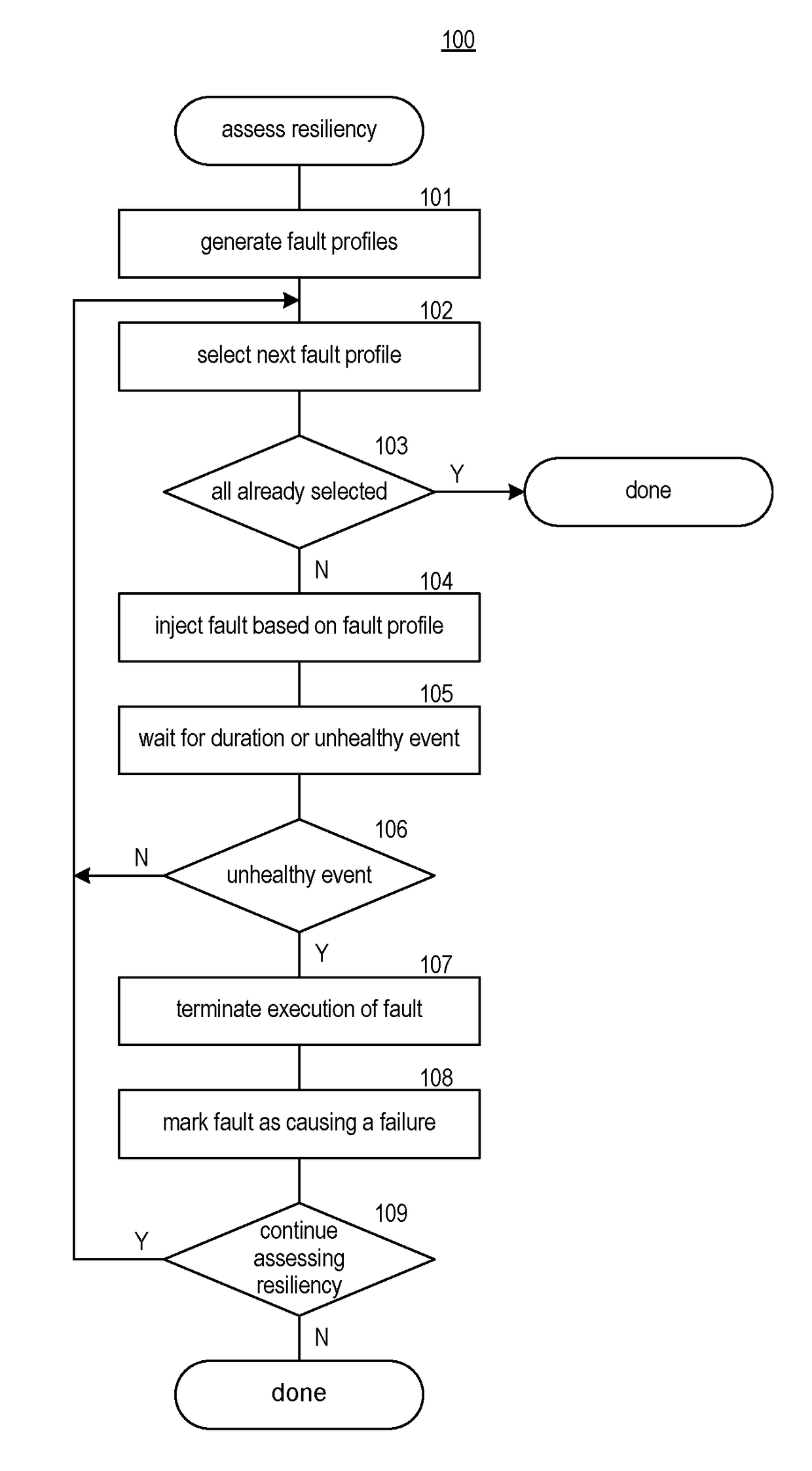
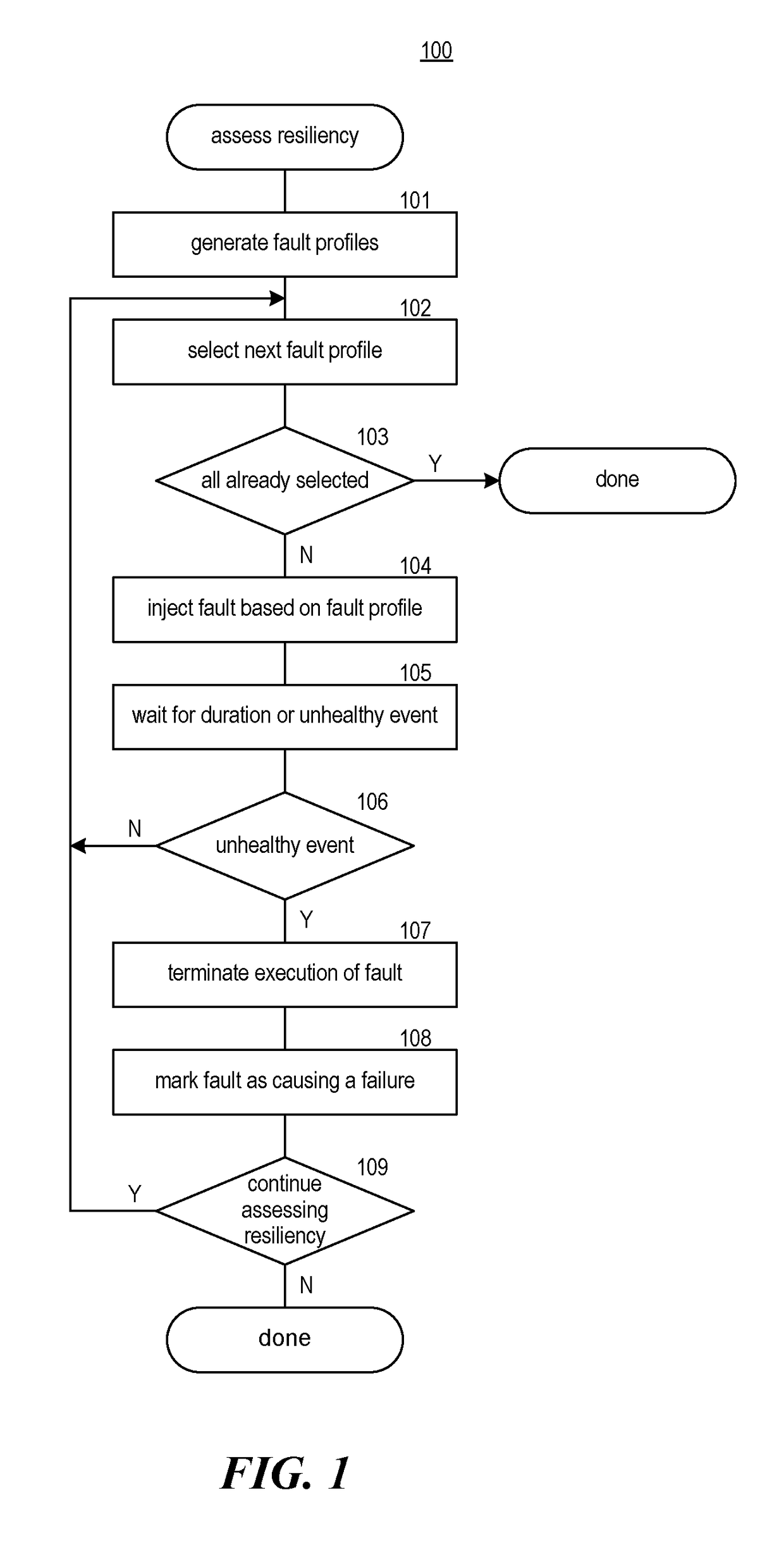
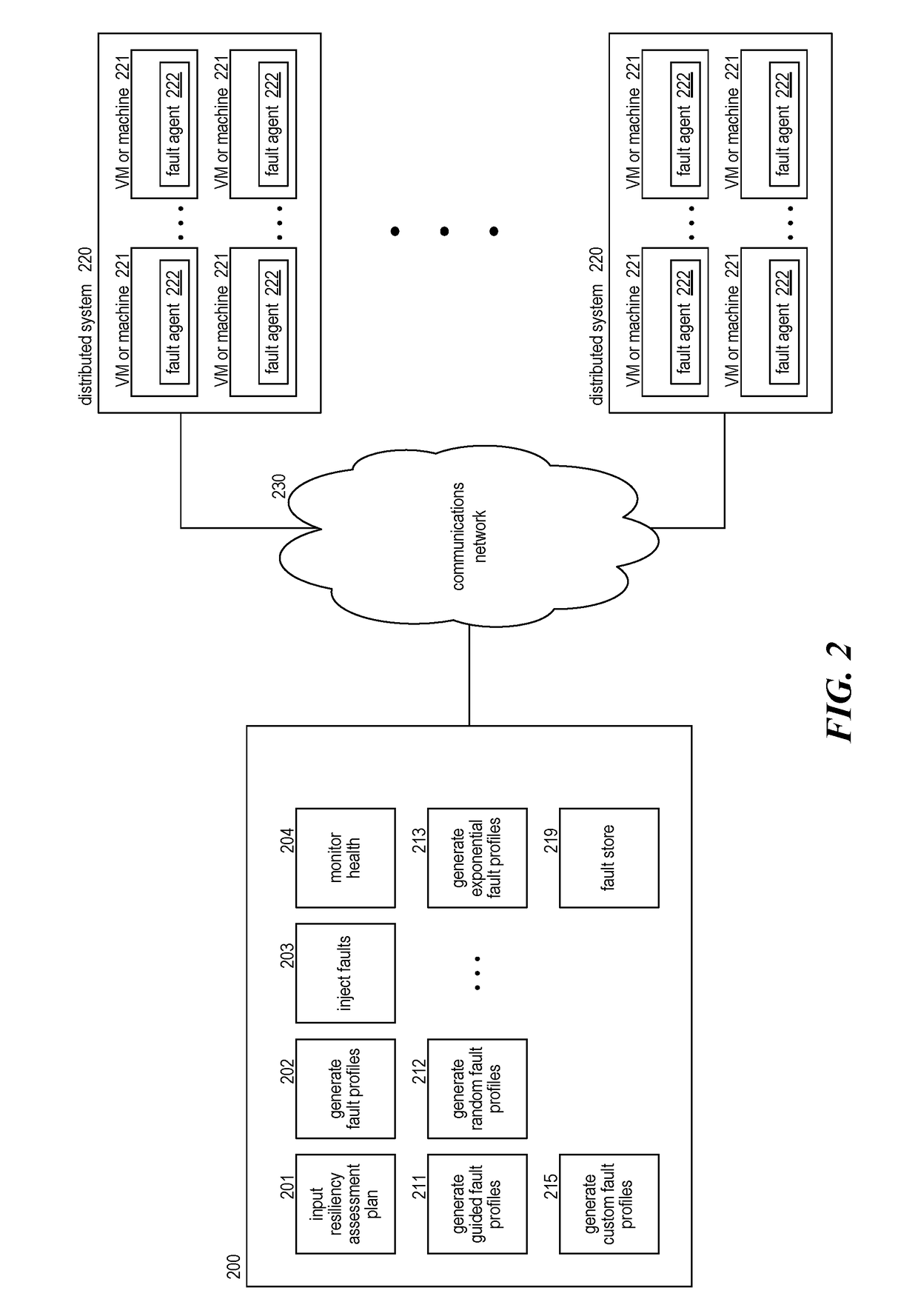
[0018]A method and system for assessing the resiliency of a distributed system is provided. A fault injection system assesses the resiliency by generating fault profiles, injecting faults based on the fault profiles, and determining whether the fault caused a failure. A fault profile specifies a value for each dimension of a fault. The dimensions of a fault may include fault type, number of machines (e.g., virtual machines), duration of the fault, configuration based on fault type, and so on. The fault type indicates the condition that may result in a fault. For example, the conditions may include excessive memory usage, excessive non-memory storage usage, excessive CPU usage, loss of computer power, a network access problem, a security problem, a process kill, restart, or crash, a corrupt file system, and change in system date, and so on. The number of machines indicates the number of machines affected by the fault. For example, the number of machines may be a percentage of the num...


PUM


Abstract

A method and system for assessing resiliency of a system is provided. A fault injection system may, for each of a plurality of dimensions of a fault profile, access an indication of possible values for the dimension, which may be specified by a user. The fault injection system may, for each of a plurality of fault profiles, automatically create the fault profile by, for each of the plurality of dimensions, selecting by the computing system a possible value for that dimension. For at least some of the fault profiles, the fault injection system injects a fault based on the fault profile into the system and determines whether a failure was detected while the fault was injected.

Description

CROSS-REFERENCE TO RELATED APPLICATION(S)[0001]This application claims the benefit of U.S. Provisional Patent Application No. 62 / 380,129 filed Aug. 26, 2016, which is incorporated herein by reference in its entirety.BACKGROUND[0002]Distributed systems are becoming more complex in their components and the interactions between their components. For example, a distributed system that provides a web interface for its users may include a front-end system that receives requests and sends responses, a back-end system that handles the requests and generates the responses, and a database system that stores and retrieves the data of the user and data of the distributed system. Each of these systems may have many components. For example, a front-end system may include a load-balancing component, a Representational State Transfer (“RESTful”) interface, a Simple Object Access Protocol interface, an Electronic Data Interchange Interface, performance monitors, security components, and so on.[0003]...

Claims


Application Information

Patent Timeline
IPC IPC(8): G06F11/26G06F11/22
CPCG06F11/2205G06F11/261G06F11/0709G06F11/2289G06F11/263G06F11/277H04L43/50G06F11/26G06F11/3409G06F11/3433G06F11/3414
Inventor PAPAK, DINKOTHANGAVEL, LENINADEVIENDEAN, JR., RICHARD GREGORYKLEMENTIEV, DMITRI A.GAKKHAR, DHRUVJAIN, VARUNZERVOS, MICHAIL
Owner MICROSOFT TECH LICENSING LLC
Learn More