
Systems, methods, and computer-accessible media for measuring or modeling a wideband, millimeter-wave channel and methods and systems for calibrating same

Active Publication Date: 2018-02-22
NEW YORK UNIVERSITY
View PDF0 Cites 19 Cited by
  • Summary
  • Abstract
  • Description
  • Claims
  • Application Information

AI Technical Summary

Benefits of technology

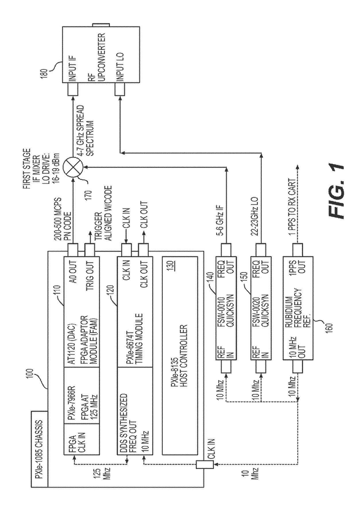
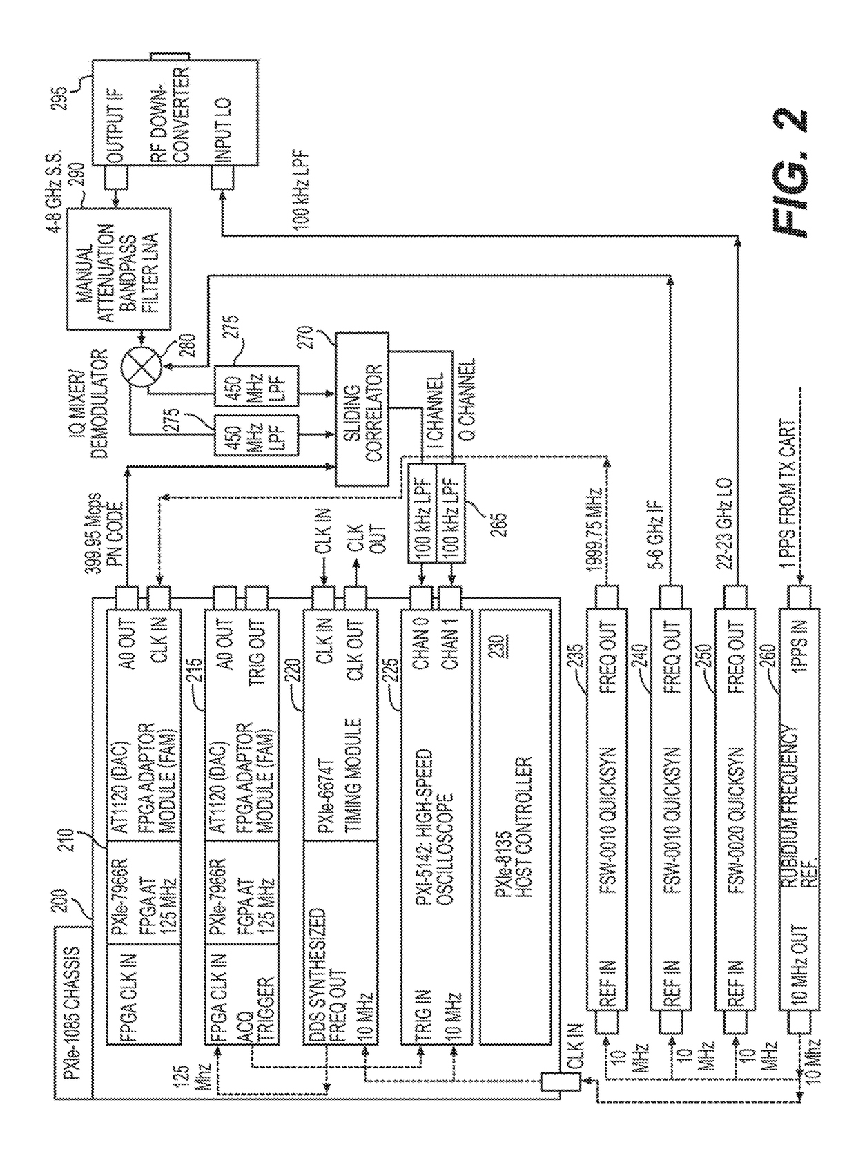
The present patent discloses methods, systems, devices, and computer-readable media for measuring parameters of wideband, millimeter-wave channels and calibrating systems used for such measurements. The technical effects of the patent include outperforming conventional methods in various applications, improving accuracy and reliability, and enhancing efficiency and productivity. The methods and systems involve measuring channel parameters based on a comparison between a first and second signal, with a controller determining calibrations and corrections based on the first and second signals. The systems include a transmitter device and a receiver device, with the transmitter device generating a pseudorandom noise code and transmitting it into the mmWave channel. The receiver device receives the transmitted signal and measures the channel parameter based on the generated code. The methods and systems can be used in various applications, such as in the calibration of wireless communication devices.

Problems solved by technology

Since such an ideal environment and line of sight conditions are very difficult—if not impossible—to replicate in a practical system implementation where mobile users are involved, there is a need for building mmW systems “in the wild,” e.g., where line-of-sight is not always available, SNRs are lower, and where mobility is the norm, so the use of static directional antennas is infeasible.
In such exemplary conditions, beamforming can boost the received signal strength but does not provide any protection against radio-channel fading, because such an arrangement does not provide diversity.
On the other hand, low mutual antenna correlation typically can result from either a sufficiently large inter-antenna spacing or different polarization directions in the array.
In relatively good channel conditions, however, the capacity of the channel becomes saturated such that further improving the SINR provides limited increases in capacity.
One challenge in designing and building such multi-antenna devices and systems can be that they must be thoroughly tested for reliability, functionality, and / or performance during development (e.g., in a design and / or qualification laboratory) and / or manufacturing.
For example, testing wireless devices can be challenging due to the unique characteristics and vagaries of the wireless channel.
While existing channel sounders may have been adequate for lower-band channels with smaller bandwidths, they are lacking in the flexibility, measurement bandwidth, and processing capacity necessary to properly measure and construct models for mmW channels where both higher bandwidths and spatial / angular directionality will be critical for proper measurement and modeling of future wireless systems that use highly directional and adaptive antenna arrays in the mobile device or base station / access point.
For example, measuring across wide bandwidths at mmW bands can be extremely difficult due to the complexity in synchronizing all frequency sources in a measurement system.
Utilizing TX and / or RX MIMO antenna systems also increases complexity, at least in terms of the number of TX-RX paths that must be measured and / or modelled.

Method used


Image

  • Systems, methods, and computer-accessible media for measuring or modeling a wideband, millimeter-wave channel and methods and systems for calibrating same
  • Systems, methods, and computer-accessible media for measuring or modeling a wideband, millimeter-wave channel and methods and systems for calibrating same
  • Systems, methods, and computer-accessible media for measuring or modeling a wideband, millimeter-wave channel and methods and systems for calibrating same

Examples


Embodiment Construction

[0014]Accordingly, to address at least some of such issues and / or problems, certain exemplary embodiments of methods, systems, devices, and computer-readable media of the present disclosure can utilize techniques to measure one or more parameters of wideband, millimeter-wave (mmW) channels and / or calibrate systems used to measure such channels. Such exemplary embodiments of methods, systems, devices, and computer-readable media of the present disclosure can vastly out-perform conventional methods, techniques and systems in various known applications, including exemplary applications discussed herein.

[0015]Some exemplary embodiments of the present disclosure comprise a system for measuring a parameter of a millimeter wave (mmW) channel, comprising: a receiver (RX) device configured to receive a first signal from the mmW channel, generate a second signal, and measure the channel parameter based on a comparison between the first and second signals; and a controller configured to determ...


PUM


Abstract

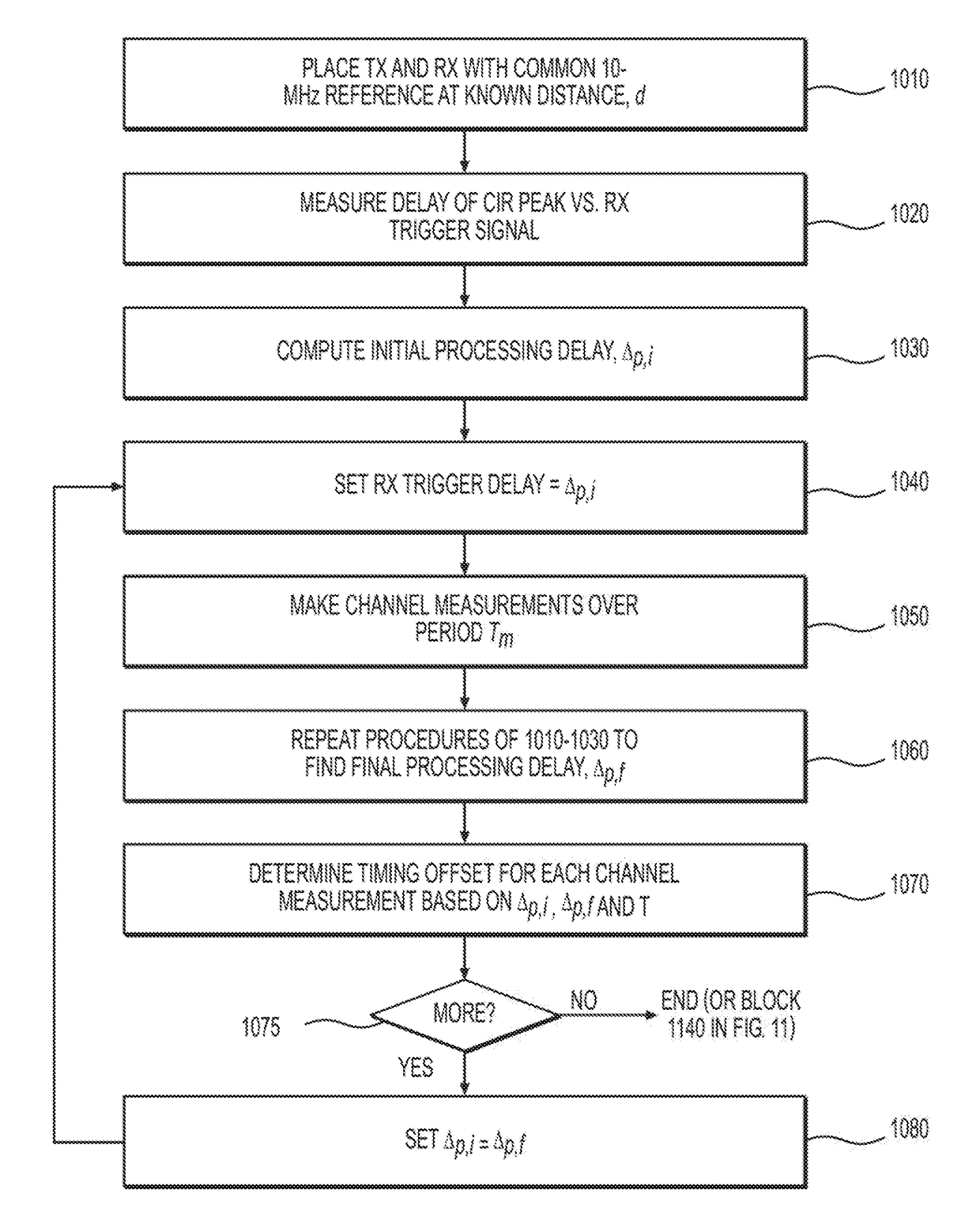
Exemplary systems and methods can be provided for measuring a parameter—e.g., channel impulse response and / or power delay profile—of a wideband, millimeter-wave (mmW) channel. The exemplary systems can include a receiver configured to receive a first signal from the channel, generate a second signal, and measure the parameter based on a comparison between the first and second signals; and a controller configured to determine first and second calibration of the system before and after measuring the parameter, and determine a correction for the parameter measurement based on the first and second calibrations. Exemplary methods can also be provided for calibrating a system for measuring the channel parameter. Such methods can be utilized for systems in which the TX and RX devices share a common frequency source and for systems in which the TX and RX devices have individual frequency sources that free-run during channel measurements.

Description

CROSS-REFERENCE TO RELATED APPLICATION(S)[0001]This application is based upon and claims the benefit of priority from U.S. Patent Application Ser. No. 62 / 121,124, filed on Feb. 26, 2015, the entire disclosure of which is incorporated herein by reference.FIELD OF THE DISCLOSURE[0002]The present application relates generally to the field of wireless communication systems, and more specifically to systems and method for measuring, modeling, and emulating electromagnetic channels and radio frequency (RF) transmit and receive circuitry that can improve the efficiency of testing electromagnetic channels eliminate the need for multiple cables, and facilitate further RF front-end designs to be easily built.BACKGROUND INFORMATION[0003]The wireless industry is en-route to another revolution with the advancement of millimeter-wave technologies and the explosion of every day electronic devices connected to the Internet in the new age of the Internet-of-Things (IoT). Since the publication of “Mi...

Claims


Application Information

Patent Timeline
IPC IPC(8): H04L7/00H04B17/21H04W56/00H04B17/309H04B17/10H04B17/11
CPCH04L7/0033H04L7/0066H04B17/21H04W56/0055H04B17/309H04B17/104H04B17/11H04B10/00H04B7/24H04B17/364H04B10/90
Inventor RAPPAPORT, THEODOREMACCARTNEY, GEORGE R.
Owner NEW YORK UNIVERSITY
Learn More