
Apparatus and Method of Wear Leveling for Storage Class Memory

a technology of storage class and wear leveling, applied in the field of memory control, can solve the problems of increasing the overhead of accessing the disk, c) and d), and the data size of interest is getting bigger and bigger

Active Publication Date: 2018-02-08
WOLLEY INC
View PDF1 Cites 16 Cited by
  • Summary
  • Abstract
  • Description
  • Claims
  • Application Information

AI Technical Summary

Benefits of technology

The invention is about how to control wear leveling for a type of memory called storage class memory. The invention determines if the data being written to the memory is a cache hit or a cache miss. If it's a cache hit, the data is written to both the cache and the actual memory location. If it's a cache miss, the data is written only to the destination in the memory. This technique helps to even out the wear and tear on the memory and ensures it lasts longer.

Problems solved by technology

Even with SSDs, there is still a big gap in response time between (c) and (d).
The different access semantics and block transfer size also increase the overhead of accessing the disk.
However, due to cost and power reason, there is a bound to this investment, especially as the Moore's Law scaling for DRAM will no longer be able to reduce cost and power much more.
Furthermore, given the overwhelming trend of cloud computing and big data applications, the data size of interest is getting bigger and bigger, and hence simply trying to increase main memory capacity will lose in this foot race.
Other than response time and capacity difference, there is also another significant difference between memory and disk.
As the functionality of a memory device is to support data written to and read from, a memory device with finite write endurance means that it cannot be written indefinitely.
If a particular memory location is being written too many times exceeding the write endurance, then the memory location cannot be used reliably for subsequent memory operations.
But since the addressing pattern is application dependent, and cannot be steered to observe the equal wear constraint, it is up to the memory subsystem to perform wear leveling without the cooperation or awareness from the host application.
Unfortunately this general table-mapping wear-leveling technique cannot be used for SCMs.
This defeats the purpose and negates the advantage of SCMs.

Method used

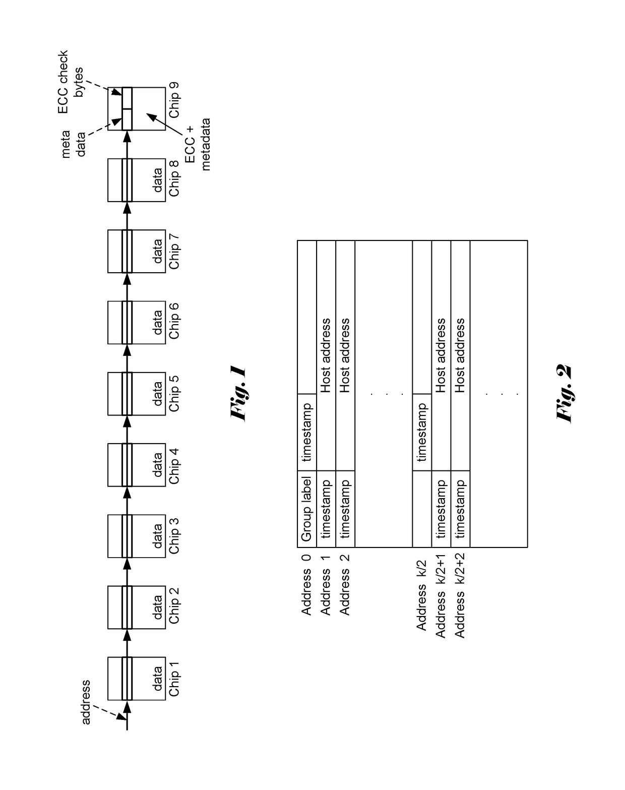

Image

  • Apparatus and Method of Wear Leveling for Storage Class Memory
  • Apparatus and Method of Wear Leveling for Storage Class Memory
  • Apparatus and Method of Wear Leveling for Storage Class Memory

Examples


Embodiment Construction

[0024]The following description is of the best-contemplated mode of carrying out the invention. This description is made for the purpose of illustrating the general principles of the invention and should not be taken in a limiting sense. The scope of the invention is best determined by reference to the appended claims.

[0025]A wear leveling technique for PCRAM has been disclosed in 2009 by Qureshi et al. (M. K. Qureshi et al., “Enhancing lifetime and security of PCM-based main memory with start-gap wear leveling”, Proceedings of the 42nd Annual IEEE / ACM International Symposium on Microarchitecture, pp. 14-23, December 2009, hereafter referred as Qureshi 2009). The so-called start-gap wear-leveling is a special form of address rotation. Address rotation is a time-varying mapping between a set of input addresses (ai1, ai2, . . . , aiN) and another set of output addresses (ao1, ao2, . . . , aoM), where M>N, and the mapping is fixed within a time period T. Different ai's will be mapped t...


PUM


Abstract

A method and apparatus of wear leveling control for storage class memory are disclosed. According to the present invention, whether current data to be written to a nonvolatile memory corresponds to a write cache hit is determined. If the current data to be written corresponds to the write cache hit, the current data are written to a write cache as well as to a designated location in the nonvolatile memory different from a destined location in the nonvolatile memory. If the current data to be written corresponds to a write cache miss, the current data are written to the destined location in the nonvolatile memory. If the current data to be written corresponds to the write cache miss and the write cache is not full, the current data is also written to the write cache. In another embodiment, the wear leveling control technique also includes address rotation process to achieve long-term wear leveling as well.

Description

FIELD OF THE INVENTION[0001]The present invention relates to memory control. In particular, the present invention relates to wear leveling for memory device in order to extend the endurance of the memory device.BACKGROUND AND RELATED ART[0002]In computer architecture the memory hierarchy is a concept used for storing and discussing performance issues in computer architectural design, algorithm predictions, and the lower level programming constructs such as involving locality of reference. The memory hierarchy in computer storage distinguishes each level in the hierarchy by response time. Since response time, complexity, and capacity are related, the levels may also be distinguished by their performance and controlling technologies.[0003]In the context of this disclosure, the memory hierarchy of interest consists of (a) processor registers, (b) caches (L1, L2, L3, etc.), (c) main memory, and (d) disk storage. For memory devices that are “farther” away from the CPU (or “lower” in the ...

Claims


Application Information

Patent Timeline
IPC IPC(8): G06F12/02G06F3/06G06F11/10G11C29/52G06F12/0804G06F12/1009
CPCG06F12/0238G06F12/0804G06F12/1009G06F11/1068G11C29/52G06F2212/403G06F3/064G06F3/0685G06F2212/1036G06F2212/608G06F3/0619G11C2029/0409G06F12/0246G06F2212/7211
Inventor SHUNG, CHUEN-SHEN BERNARD
Owner WOLLEY INC
Learn More