
Secure Controlled Substance Pill Dispensing Device

Inactive Publication Date: 2018-02-01
PATTON JIM
View PDF21 Cites 6 Cited by
  • Summary
  • Abstract
  • Description
  • Claims
  • Application Information

AI Technical Summary

Benefits of technology

The patent describes a pill dispensing device that includes a container, a lid, and a dispensing assembly. The device includes a tamper resistance mechanism that can detect and prevent any tampering with the device. The dispensing assembly includes a hopper, chutes, sensors, and a plate driving assembly. The device can release pills when certain parameters are met and render them unusable if the device is tampered with. The patent aims to provide a safe and secure pill dispensing device that can prevent unauthorized access and maintain the purity of the pills.

Problems solved by technology

Any tampering with the device will likely result in a rupture to that space, such that the conductive solution will escape.
Such substances are configured such that any disruption to the integrity of the substance will result in a detectable change in the electrical current.
The tamper resistance fluid renders the pills unusable when it is dispensed from the through the jets.
The device is capable of releasing pills upon certain parameters being met, and rendering pills unusable if the device is tampered with.

Method used


Image

  • Secure Controlled Substance Pill Dispensing Device
  • Secure Controlled Substance Pill Dispensing Device
  • Secure Controlled Substance Pill Dispensing Device

Examples


first embodiment

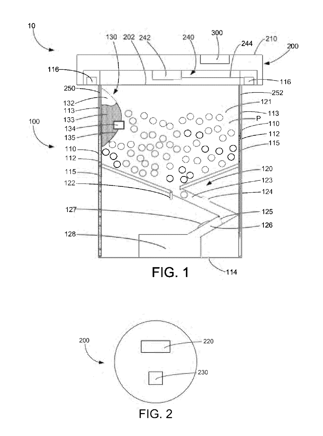
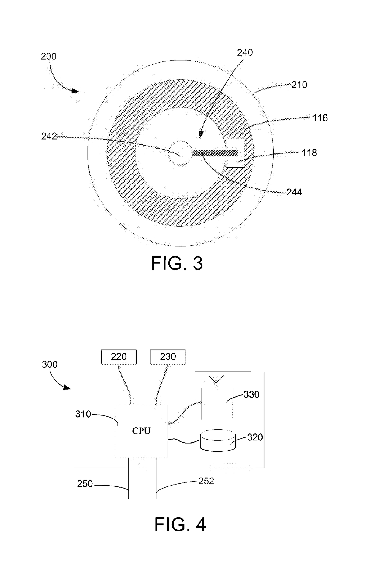
[0017]In the first embodiment, the container 100 is preferably cylindrical and includes a first cylinder 110, a second cylinder 112, a bottom 114, a top ring 116, a dispensing mechanism 120 and a tamper resistance mechanism 130. The first cylinder 110 and second cylinder 112 are formed so that the diameter of the first cylinder 110 is greater than the diameter of the second cylinder 112. Both the first cylinder 110 and second cylinder 120 engage the bottom 114. It is understood that the positioning of the first cylinder 110 and the second cylinder 112 forms a space 113 between the first cylinder 110 and second cylinder 112. This space 113 is filled with a conductive liquid 115 capable of conducting an electric current. The space 113 may otherwise be filled with a material capable of producing electric current, such as wiring, a pad, foam, or a screen. The material capable of producing electric current may be attached to the inside of the container 100 by an adhesive, instead of occu...

second embodiment

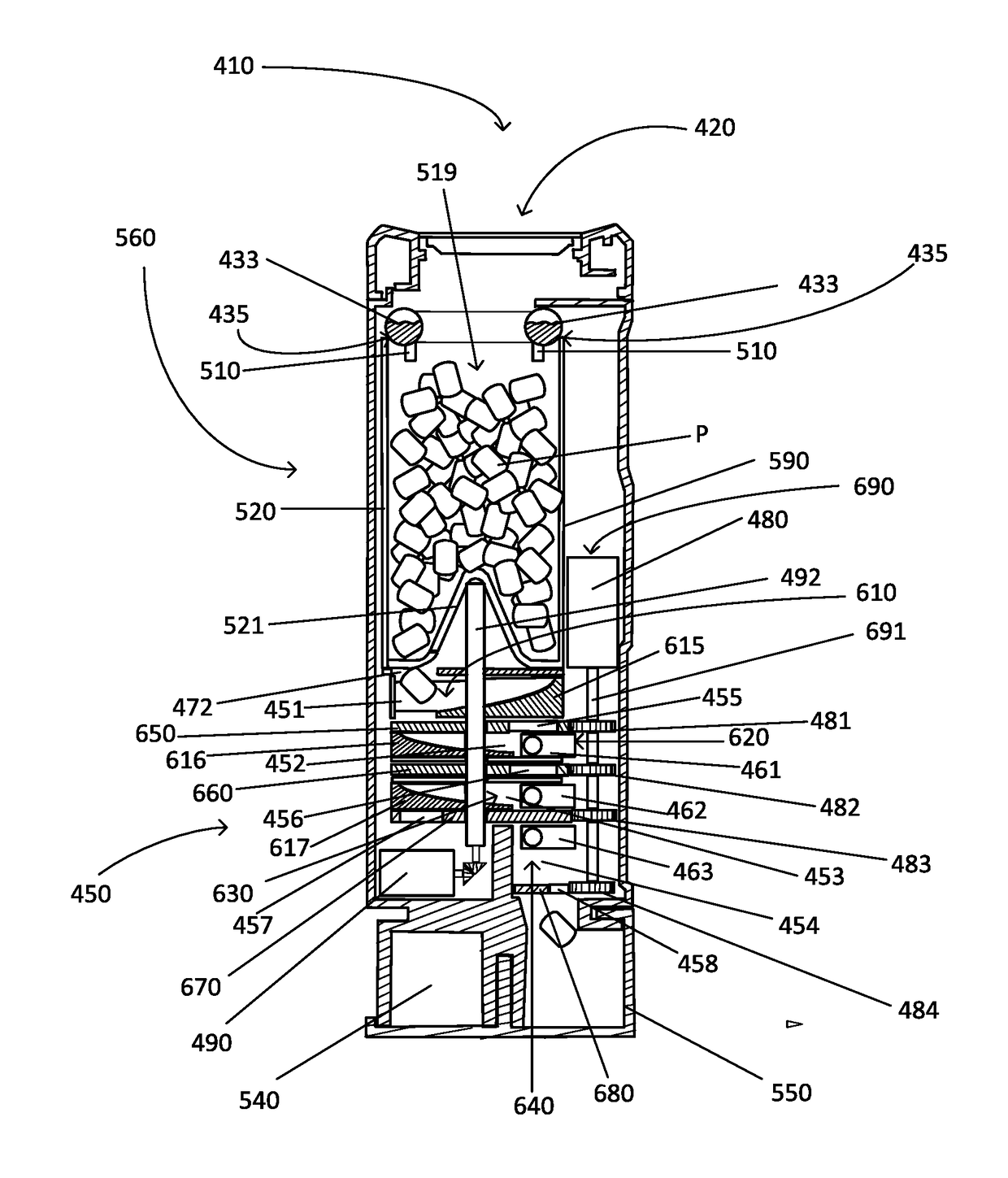
[0026]In a preferred second embodiment, FIG. 5 shows a side view of a pill dispensing device 410. The pill dispensing device 410 includes a lid 420 and a container 560. The lid 420 engages the container 560, via a servo lock, or alternatively the lid 420 and container 560 may be threadably engaged. The container 560 includes a locking mechanism 430, which allows the user to enter a code and receive a pill if certain parameters are met, and a label 530. As depicted in FIG. 5, the locking mechanism 430 uses a letter combination, but it will be understood that color or number combinations could replace the letter combination. While FIG. 5 depicts the label 530 as a metal-type material adhered to the side of the container 560, it will be understood that the label 530 may be made of any other type of material known in the art that is disposable and can be adhered to the side of the container 560. Such materials include, but are not limited to, paper and plastic. Alternatively, the label ...


PUM


Abstract

A pill dispensing device includes a lid with an RFID reader and a container that engages that lid. The container includes a hopper that is configured to hold a plurality of pills and a tray that is connect that hopper. The container can dispense a pill from the hopper into the tray when an authorized RFID rob is read by the RFID reader. The pill dispensing device may include a code entry mechanism on the side of the container. The code entry mechanism activates or deactivates a lock. The lock is capable of securing the lid to the container. The pills are dispensed through the pill dispensing device when certain parameters are met. If the device it tampered with, the pills may be rendered unusable by a tamper resistance mechanism.

Description

RELATED APPLICATIONS[0001]This application is related to and claims the benefit of United States Patent Application No. 2014 / 704,475, filed May 5, 2015, and United States Patent Application No. 2014 / 704,570, filed May 5, 2015, both of which are hereby incorporated by reference.FIELD OF THE INVENTION[0002]The present invention generally relates to the field of medication packaging and particularly to the dispensing of pills.BACKGROUND OF THE INVENTION[0003]The health industry is faced with a multibillion dollar problem of prescription controlled drug abuse. Patients often either inadvertently or intentionally take their medication too frequently or outside the guidance of their treating physician. This problem is exacerbated when unauthorized persons attempt to utilize pills or other prescribed medication from an authorized patient's pill supply. Accordingly, there is a need for a secure pill dispensing device that will ensure that patients do not take their medication more frequentl...

Claims


Application Information

Patent Timeline
IPC IPC(8): A61J7/00A61J7/04A61J7/02
CPCA61J7/0076A61J7/0069A61J2200/42A61J7/04A61J2205/60A61J7/02A61J2205/20A61J7/0481A61J1/1437
Inventor PATTON, JIMBARR, JOHNWERBICKAS, ALEXANDERBAILEY, PATRICKLOSAW, JEREMYPEREZ, JUAN CARLOSMCNEIL, RAESHONHYMEL, CORY
Owner PATTON JIM
Learn More