Sending Communication Between a Remote Device and a Control Server
- Summary
- Abstract
- Description
- Claims
- Application Information
AI Technical Summary
Benefits of technology
Problems solved by technology
Method used
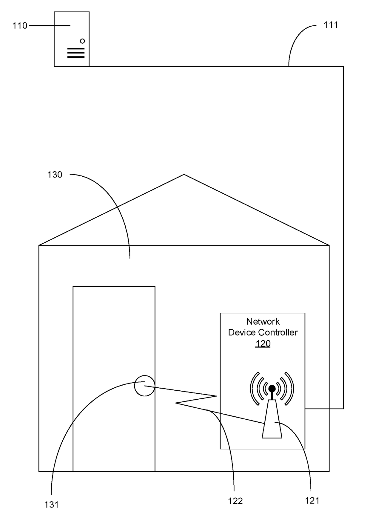
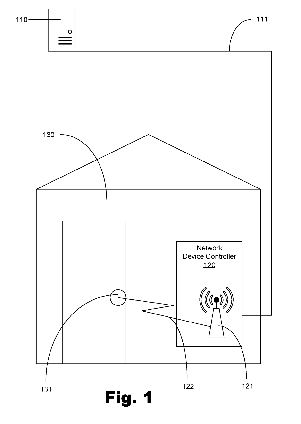
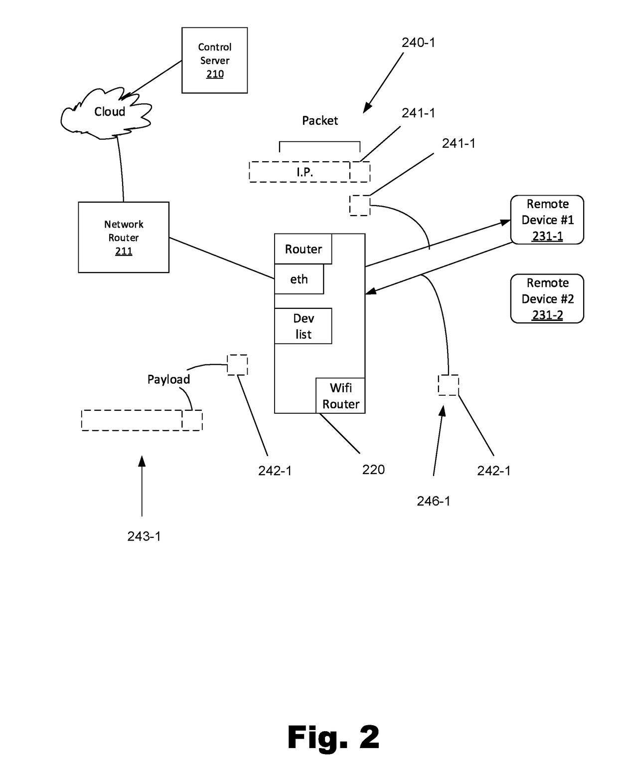
Image

Examples
Embodiment Construction
[0031]A detailed description of the claimed invention is provided below by example, with reference to examples in the appended figures. Those of skill in the art will recognize that the components and steps of the invention as described by example in the figures below could be arranged and designed in a wide variety of different configurations without departing from the substance of the claimed invention. Thus, the detailed description of the examples in the figures is merely representative examples of the invention, and is not intended to limit the scope of the invention as claimed.
[0032]In some instances, numerical values are used to describe features such as spreading factors, output power, bandwidths, link budgets, data rates, and distances. Though precise numbers are used, one of skill in the art recognizes that small variations in the precisely stated values do not substantially alter the function of the feature being described. In some cases, a variation of up to 50% of the s...
PUM
 Abstract
Description
Claims
Application Information
 - R&D
- Intellectual Property
- Life Sciences
- Materials
- Tech Scout
- Unparalleled Data Quality
- Higher Quality Content
- 60% Fewer Hallucinations
Browse by: Latest US Patents, China's latest patents, Technical Efficacy Thesaurus, Application Domain, Technology Topic, Popular Technical Reports.
© 2025 PatSnap. All rights reserved.Legal|Privacy policy|Modern Slavery Act Transparency Statement|Sitemap|About US| Contact US: help@patsnap.com