X-ray generator

a generator and x-ray technology, applied in the direction of x-ray tube targets, x-ray tubes, nuclear engineering, etc., can solve the problems of difficult narrowing of the electron beam that spreads from an electron source, and the increase of the x-ray focal spot diameter, so as to facilitate the position of the x-ray low absorption rate part and facilitate the irradiation of the electron beam

Active Publication Date: 2018-01-04
SHIMADZU CORP
View PDF1 Cites 2 Cited by
  • Summary
  • Abstract
  • Description
  • Claims
  • Application Information

AI Technical Summary

Benefits of technology

[0026]According to the invention, since an X-ray low absorption rate part in which an X-ray absorption rate is locally low is provided in an irradiation region of an electron beam in a target stacked structure obtained by integrally stacking a target and an X-ray irradiation window, and substantially only an X-ray from the X-ray low absorption rate part among X-rays generated by irradiation of the electron beam is extracted to the outside, an X-ray focal spot diameter depend

Problems solved by technology

However, it is extremely difficult to narrow the electron beam that spreads from an electron source due to a problem of an aberration of a lens that narrows the electron beam.
Howeve

Method used


Image

  • X-ray generator
  • X-ray generator
  • X-ray generator

Examples


Embodiment Construction

[0038]Hereinafter, embodiments of the invention will be described with reference to drawings.

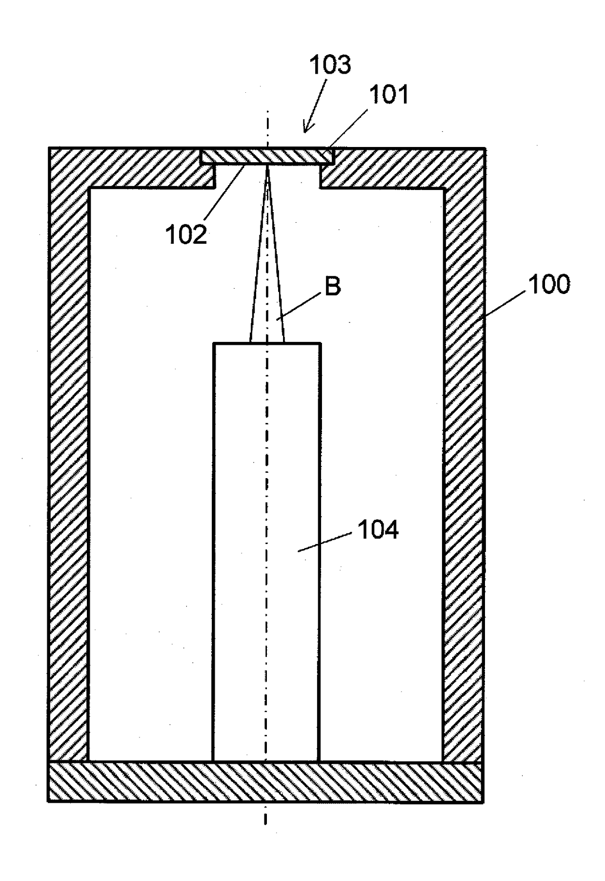
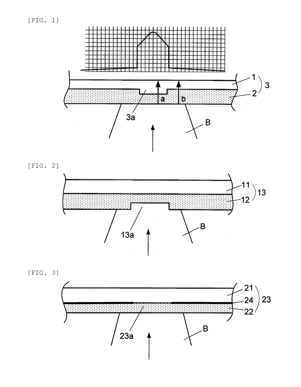
[0039]FIG. 1 is a schematic cross-sectional view of a main part of an embodiment of the invention and a graph indicating an X-ray profile emitted to the outside by this configuration. In this embodiment, a basic configuration as an X-ray generator is the same as that illustrated in FIG. 8, and a great feature is that a target stacked structure is changed from that illustrated in FIG. 9 to that illustrated in FIG. 1.

[0040]A target stacked structure 3 fixed to close one end portion of a vacuum container includes an X-ray irradiation window 1 and a target 2 stacked on an inner surface side of the container similarly to that of FIG. 9. Further, an electron beam B accelerated and focused from an electron gun in the vacuum container is emitted onto the target 2 to generate an X-ray. In general, W, Mo, Cu, etc. is used as a material of the target 2, and Al, Be, diamond, etc. is used for the X-ray i...


PUM


Abstract

An X-ray generator capable of reliably reducing an X-ray focal spot size without depending on the focal spot size of an electron beam on a target. Providing, within the irradiation range of an electron beam B of a target laminated structure 3 comprising a target 2 and an X-ray irradiation window 1, a low X-ray absorptivity region 3a of localized low X-ray absorptivity in the irradiation direction of the electron beam B results in the suppression of emission to the outside of X-rays from among the X-rays generated as a result of the irradiation of the electron beam B onto the target 2 that are from regions other than the low X-ray absorptivity region 3a, and an X-ray focal spot of a size corresponding to the size of the low X-ray absorptivity region 3a is obtained regardless of the size of the irradiation region of the electron beam B.

Description

TECHNICAL FIELD[0001]The present invention relates to an X-ray generator used for an industrial X-ray inspection apparatus, a medical X-ray inspection apparatus, or various X-ray analysis apparatuses or measurement apparatus using diffraction or refraction of an X-ray, and more specifically relates to a transmission type X-ray generator that extracts an X-ray generated by causing an electron to collide with a target in a vacuum container to the outside of the vacuum container around a direction along a traveling direction of the electron.BACKGROUND ART[0002]An X-ray generator of a type in which an X-ray is generated by irradiating a target with an electron beam in a vacuum container uses a reflective type target that extracts an X-ray in a different direction from a traveling direction of an electron or a transmission type target that extracts an X-ray in substantially the same direction as a traveling direction of an electron. In the X-ray generator using the reflective type target...

Claims


Application Information

Patent Timeline
IPC IPC(8): G21K5/04G21K5/08
CPCG21K5/04G21K5/08H01J2235/183H01J35/116H01J35/186H01J35/18H01J2235/08
Inventor MIYAOKA, AKIHIRO
Owner SHIMADZU CORP
Why Eureka
Try Eureka