Vehicle headlamp
a headlamp and headlamp technology, applied in the field of headlamps, to achieve the effect of reducing the number of components, reducing weight, and reducing costs
- Summary
- Abstract
- Description
- Claims
- Application Information
AI Technical Summary
Benefits of technology
Problems solved by technology
Method used
Image
Examples
first embodiment
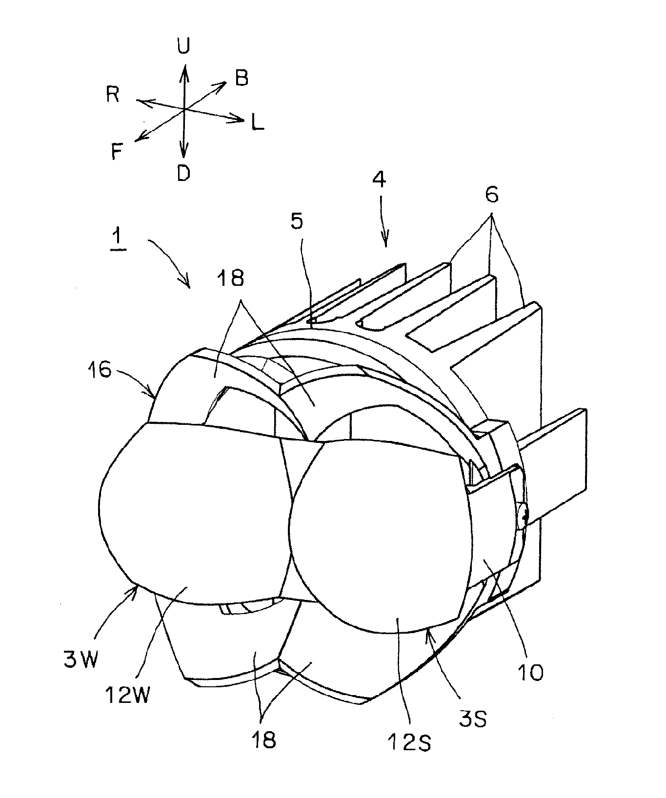
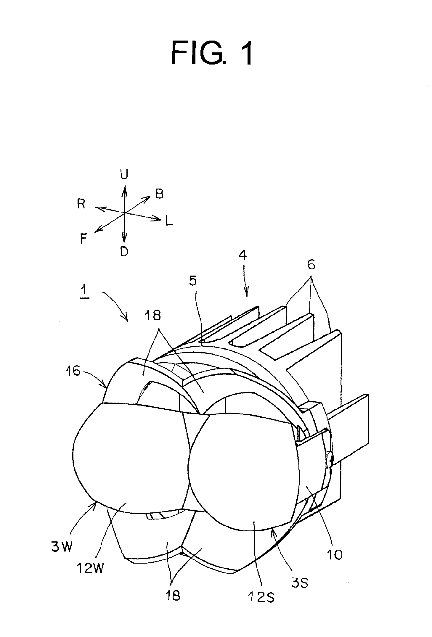
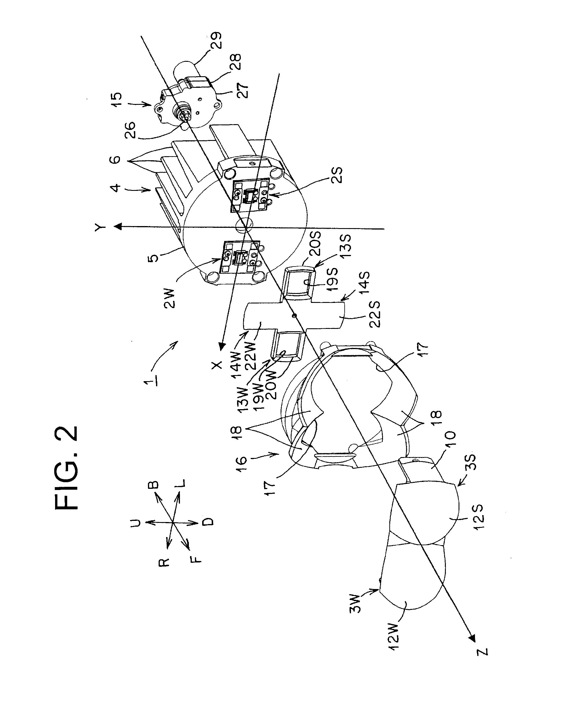
[0125]FIGS. 1 to 35 show a first embodiment of a vehicle headlamp according to the present invention. Hereinafter, a constitution of the vehicle headlamp of the first embodiment will be described. In the figures, reference numeral 1 designates a vehicle headlamp (automobile headlamp) of the first embodiment. The vehicle headlamp 1 is a vehicle headlamp for left-side cruising lane. A vehicle headlamp for right-side cruising lane is reversed at the left and right in the vehicle headlamp 1 for left-side cruising lane. In addition, in FIG. 2, the X, Y, and Z axes constitute an orthogonal coordinate system (X-Y-Z orthogonal coordinate system). The X axis corresponds to a horizontal axis in a transverse direction and an opposite lane side. In other words, in the first embodiment, the right side R corresponds to a positive direction and the left side L corresponds to a negative direction. In addition, the Y axis corresponds to a vertical axis in a longitudinal direction, and in the first e...
second embodiment
[0200]FIGS. 36 to 38 show a second embodiment of a vehicle headlamp according to the present invention. Hereinafter, the vehicle headlamp of the second embodiment will be described. In the figures, like constituent elements shown in FIGS. 1 to 35 are designated by like reference numerals.
[0201]The vehicle headlamp of the second embodiment is intended to illuminate: a light distribution pattern LP for low beam, shown in FIG. 32; a light distribution pattern HP for high beam, shown in FIG. 35; and a light distribution pattern MP for mid beam, shown in FIG. 38, toward a forward direction of a vehicle. The light distribution pattern MP for mid beam, shown in FIG. 38, has a substantially horizontal cutoff line CL. The cutoff line CL of the light distribution pattern MP for mid beam, shown in FIG. 38, is positioned more upside than cutoff lines CL1, CL2, CL3 of the light distribution pattern LP for low beam, shown in FIG. 32.
[0202]The vehicle headlamp of the second embodiment is provided ...
PUM
 Abstract
Description
Claims
Application Information
 - R&D
- Intellectual Property
- Life Sciences
- Materials
- Tech Scout
- Unparalleled Data Quality
- Higher Quality Content
- 60% Fewer Hallucinations
Browse by: Latest US Patents, China's latest patents, Technical Efficacy Thesaurus, Application Domain, Technology Topic, Popular Technical Reports.
© 2025 PatSnap. All rights reserved.Legal|Privacy policy|Modern Slavery Act Transparency Statement|Sitemap|About US| Contact US: help@patsnap.com


