
Blade drive device and optical instrument

a drive device and optical instrument technology, applied in the direction of shutters, instruments, camera diaphragms, etc., can solve the problems of less likely increased size of electromagnetic actuators, and unexpected movement of front curtain and rear curtain in closing direction, so as to achieve quickening of shutter operation and impact resistance

Active Publication Date: 2018-01-04
SEIKO GRP CORP
View PDF44 Cites 2 Cited by
  • Summary
  • Abstract
  • Description
  • Claims
  • Application Information

AI Technical Summary

Benefits of technology

The invention is about a blade drive device and optical instrument that can be made smaller, have quicker shutter operation, and be impact resistant. The device uses an electromagnetic actuator with a detent torque to hold the front and rear curtains in place when power is not supplied. However, increasing the detent torque can make the actuator larger. The invention solves this problem by allowing the blade position holding mechanism to be locked by both the front and rear curtain locking portions, so the curtains cannot be unexpectedly moved in the closing direction by a drop impact. This ensures that the device is reliable and impact resistant. The optical instrument, which includes the blade drive device, is miniaturized and reliable with impact resistance.

Problems solved by technology

However, according to the electromagnetic drive-type FP shutter, if the detent torque of the electromagnetic actuator is increased in order to improve a holding force of the front curtain and the rear curtain when the power is not supplied, a shutter operation is less likely to be quickened, and the increased detent torque results in an increased size of the electromagnetic actuator.
On the other hand, if the detent torque of the electromagnetic actuator is decreased in order to quicken the shutter operation, there is a possibility that the front curtain and the rear curtain may be unexpectedly moved in a closing direction due to a drop impact.

Method used


Image

  • Blade drive device and optical instrument
  • Blade drive device and optical instrument
  • Blade drive device and optical instrument

Examples


Embodiment Construction

[0029]Next, an embodiment according to the invention will be described with reference to the drawings.

[0030]Optical Instrument

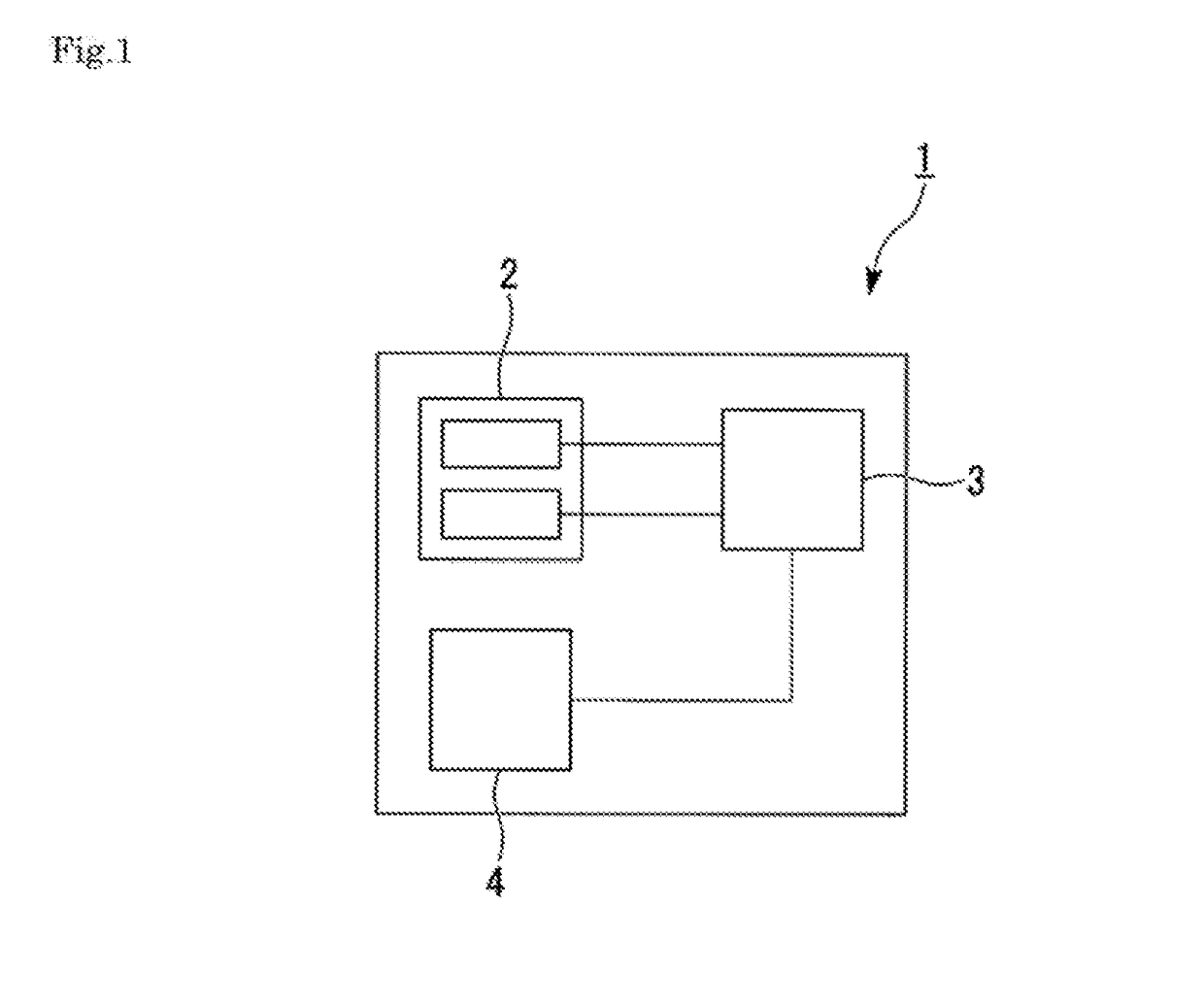
[0031]FIG. 1 is a block diagram of an optical instrument 1.

[0032]As illustrated in FIG. 1, for example, the optical instrument 1 is used as a mirrorless single lens camera or a digital single lens reflex camera. The optical instrument 1 includes an FP shutter (blade drive device) 2, a control unit 3, and an imaging element 4.

[0033]The control unit 3 controls an overall operation of the optical instrument 1. For example, the control unit 3 includes a CPU, a ROM, and a RAM.

[0034]For example, the imaging element 4 is a CCD or a CMOS image sensor. The imaging element 4 converts an object image formed by light into an electric signal.

[0035]The optical instrument 1 includes a lens (not illustrated) for adjusting a focal length.

[0036]FP Shutter

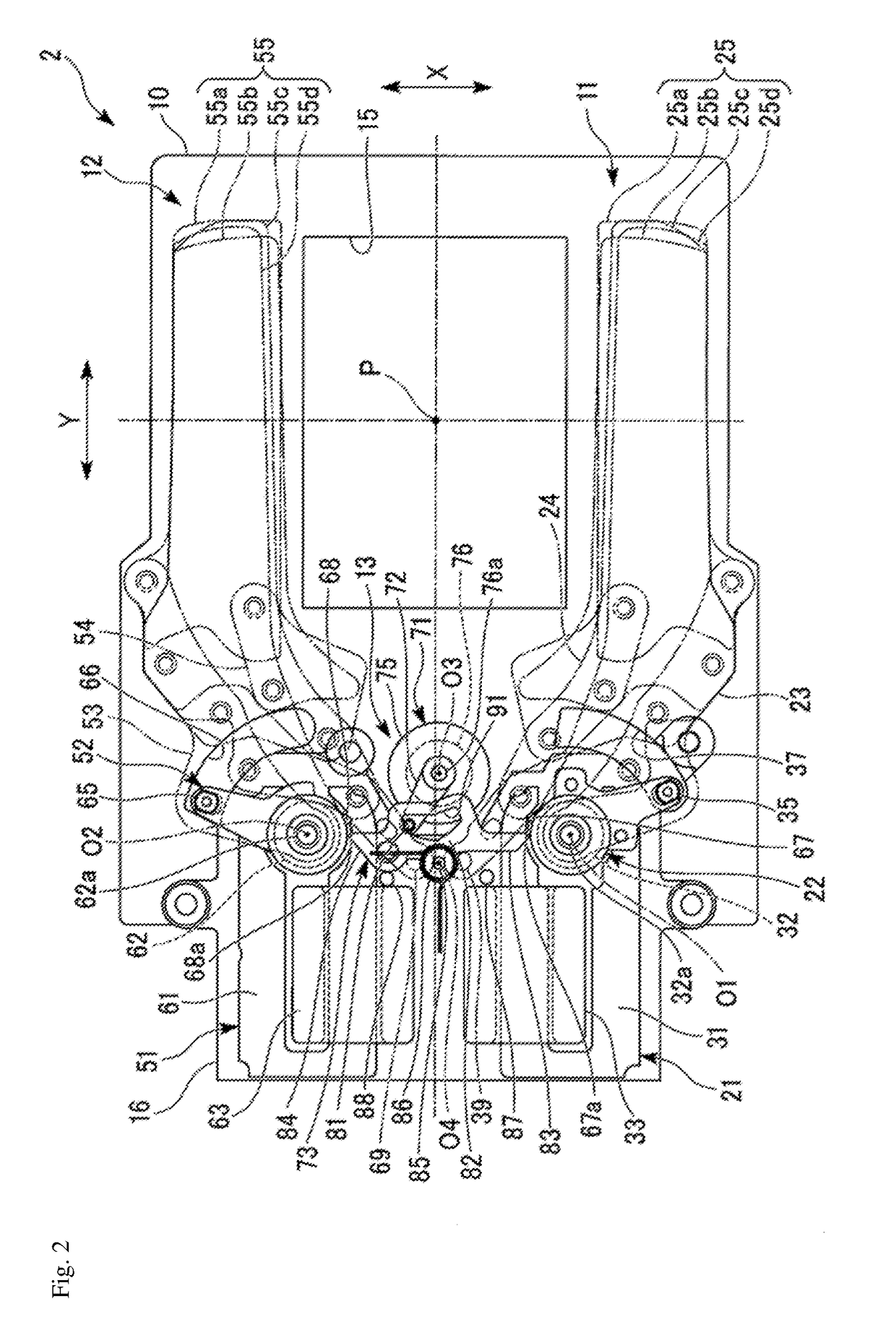
[0037]FIG. 2 is a plan view illustrating a state where a blade position holding mechanism 13 is located at an entry position...


PUM


Abstract

There is provided a blade drive device including a substrate that has an opening, a front curtain and a rear curtain that are movable along an opening surface of the opening so as to open and close the opening, a front curtain electromagnetic actuator that actuates the front curtain, a rear curtain electromagnetic actuator that actuates the rear curtain, and that is capable of holding the rear curtain at an open position in a state having no power supply, a front curtain locking portion that interlocks with opening and closing operations of the front curtain, a rear curtain locking portion that interlocks with opening and closing operations of the rear curtain, and a blade position holding mechanism that is capable of entry and escape between an entry position which enters each operation trajectory of the front curtain locking portion and the rear curtain locking portion in response to the opening and closing operations of the front curtain and the rear curtain and an escape position escaped from the operation trajectory. At the entry position, the blade position holding mechanism can engage with both the front curtain locking portion and the rear curtain locking portion, thereby regulating the movement of the front curtain and the rear curtain in the closing direction.

Description

RELATED APPLICATIONS[0001]This application claims priority under 35 U.S.C. §119 to Japanese Patent Application No. 2016-128787 filed on Jun. 29, 2016, the entire content of which is hereby incorporated by reference.BACKGROUND OF THE INVENTIONField of the Invention[0002]The present invention relates to a blade drive device and an optical instrument.Background Art[0003]An optical instrument such as a digital camera is equipped with a focal plane shutter (hereinafter, referred to as an FP shutter) in order to control exposure to an imaging element. The FP shutter has a substrate which has an opening (picture frame), and a front curtain and a rear curtain which are movable along an opening surface of the opening so as to open and close the opening.[0004]For example, JP-A-2014-170022 discloses a so-called electromagnetic drive-type FP shutter which actuates the front curtain and the rear curtain by using an electromagnetic actuator. Compared with a so-called spring drive-type FP shutter ...

Claims


Application Information

Patent Timeline
IPC IPC(8): G03B9/14
CPCG03B9/14G03B9/08G03B9/40G02F1/0551G03B9/02G02B26/004H04N23/55
Inventor NAKANO, YOICHI
Owner SEIKO GRP CORP
Learn More