Automated system for producing connectorized equipment and managing the production thereof

a technology of automatic system and connectorized equipment, which is applied in the manufacture of contact member cases/bases, lamp testing, contact member assembly/disassembly, etc., can solve the problems of limited work scope, unpredictable delays, and limitations in the performance of existing handheld testers and ates

Active Publication Date: 2017-12-28
ZIOTA TECH
View PDF2 Cites 5 Cited by
  • Summary
  • Abstract
  • Description
  • Claims
  • Application Information

AI Technical Summary

Benefits of technology

The patent describes a method to create universal mating interface cables and test programs quickly using a centralized database containing information about all types and models of connectors. This allows for the creation of test programs and the ability to remotely operate to create, validate, and track mating interfaces and test programs. The system also uses automated test equipment to assist in the manufacturing and repairing of connectorized electrical equipment, which can help increase operational capabilities, accelerate production, lower costs, and improve productivity. Additionally, the system allows for the creation of modular panels and cables that can be easily installed and maintained on a ship or other platforms. This can help reduce the cost of ownership of the electrical sub-system over the life of the platform and improve its performance.

Problems solved by technology

The limitations in the performance of existing handheld testers and ATEs are mostly related to the ability of a technician to use them efficiently to deliver or return to service the SUT.
The handheld testers are generally very agile as they can be used on any connection point using generic probes on specific connections, but are limited in the scope of work that can be performed by a technician who is testing only a few test points at a time.
Opportunity costs of the operator of the SUT to wait for the interface cable to be able to use the ATE to make urgent repairs.
However, the faulty part of electrical equipment is not always available on the spot, causing unpredictable delays.
Furthermore, ATEs are conventionally used in very limited manufacturing applications such as quality control testing of the integrity of electrical circuits and functional tests and in very limited maintenance applications such as troubleshooting and locating electrical faults.
The process is done in a very hard-working environment, requires extensive manual testing and provides limited opportunities for automated maintenance.

Method used


Image

  • Automated system for producing connectorized equipment and managing the production thereof
  • Automated system for producing connectorized equipment and managing the production thereof
  • Automated system for producing connectorized equipment and managing the production thereof

Examples


Embodiment Construction

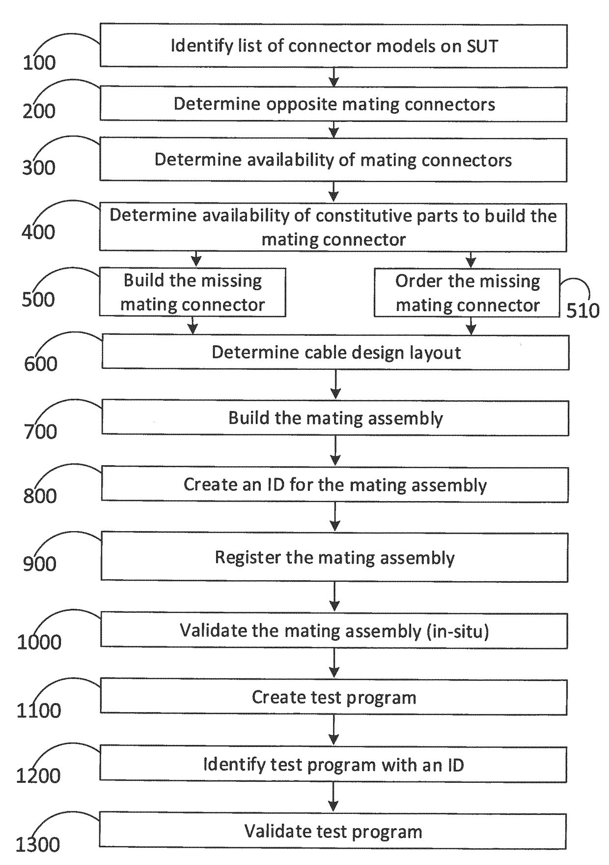
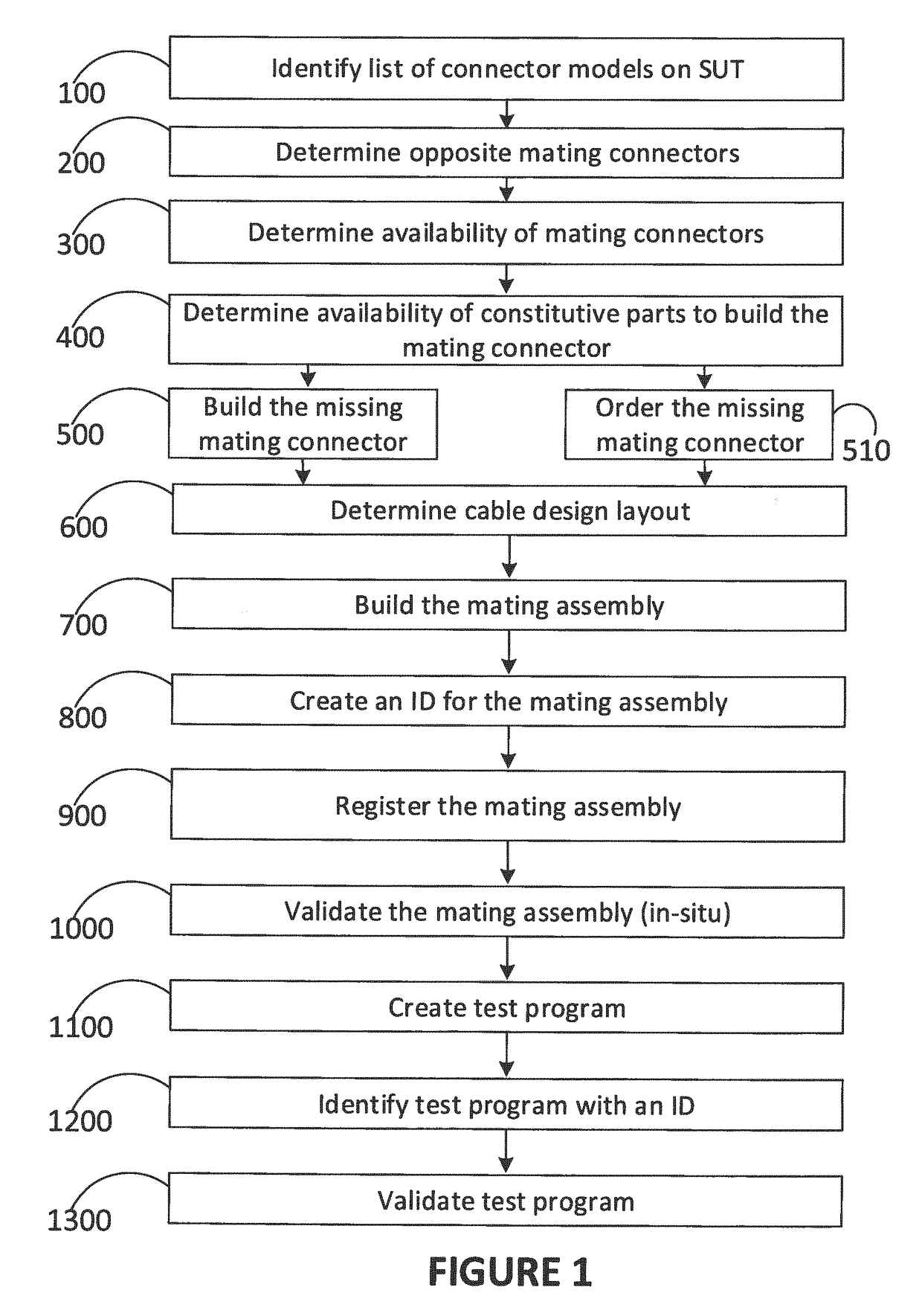
[0095]When, at the beginning of or during a testing of electrical equipment, it is noted that a part of test equipment is faulty, missing or incomplete, there is a need to fulfill this need promptly. The same applies to a part of electrical equipment to be tested, since the inability to repair or replace a faulty part of electrical equipment may have the same effect of delaying the workflow, and postponing the moment when the electrical equipment is put back in service. The electrical equipment may comprise electrical cables, electrical harnesses, electrical components such as relays, coil, control panels and all sorts of parts in a connectorized electrical equipment. The term “connectorized” electrical equipment encompasses electrical equipment which have at least one connector, with wires connected thereto. The connectorized electrical equipment may comprise a mix of parts such as wire harnesses, or pair of connectors with wires connected therebetween, or a connector having wires ...


PUM

PropertyMeasurementUnit
electricalaaaaaaaaaa
Electrical testsaaaaaaaaaa
timeaaaaaaaaaa

Abstract

There is described a method for assembling a connectorized electrical equipment. A connectivity list required for the connectorized electrical equipment is provided, comprising an origin connector and its identifier, a destination electrical equipment subpart and its identifier thereof; and a list of connections between the origin connector and the destination electrical equipment subpart. By querying a database comprising a library of connectors, a construction plan is generated for the connectorized electrical equipment. The construction plan includes diagrams for assembly, images to assist the assembler, a list of material for managing inventory and instructions. An ATE can be connected to the connectorized electrical equipment to be assembled. Based on the construction plan, instructions are provided for a connection between the origin connector and the destination electrical equipment subpart. Connections can be made manually or using the ATE. All connections are registered in real time for progression tracking and instruction updates.

Description

CROSS-REFERENCE TO RELATED APPLICATIONS[0001]This application claims benefit of U.S. patent application Ser. No. 14 / 230,955 filed Mar. 31, 2015, which claims priority of U.S. provisional patent application 61 / 806,899 filed Mar. 31, 2013, the specification of which is hereby incorporated herein by reference in its entirety.BACKGROUND(a) Field[0002]The subject matter disclosed generally relates to automated testing equipment for connectorized electrical equipment, and to the connectorized electrical equipment.(b) Related Prior Art[0003]Electrical tests and maintenance of electrical equipment are performed using portable handheld testers such as multi-meters and automated test equipment (ATE) such as wiring analyzers and other bench testers to perform validation of integrity or functional tests.[0004]One of the main drivers for the type of equipment to use is the availability of interface cables to connect to the various connection points of the subject under test (SUT) on a timely bas...

Claims


Application Information

Patent Timeline
Patent Type & Authority Applications(United States)
IPC IPC(8): G01R31/28H01R43/18H01B7/32B33Y50/00G06Q20/12G05B19/4099G06F17/30H01R43/20H01B7/00G06Q10/08
CPCG01R31/2834G06F17/30528G06Q20/1235G05B19/4099H01B7/0045H01B7/32H01R43/18H01R43/20B33Y50/00G06Q10/087G05B2219/49023G01R31/44G01R1/0416Y10T29/49117Y10T29/532G06F16/24575G06F2113/16G06F30/17
Inventor LUSSIER, ALAIN
Owner ZIOTA TECH
Why Eureka
Try Eureka