
Seat backrest and seat including the same

a seat backrest and seat technology, applied in the field of seat backrests, can solve the problems of poor absorbing poor weight reduction of seat backrests, and poor density of carbon steel, and achieve the effects of reducing weight, facilitating manufacturing, and facilitating absorption and discharging of impact for

Active Publication Date: 2017-12-28
BASF AG
View PDF1 Cites 9 Cited by
  • Summary
  • Abstract
  • Description
  • Claims
  • Application Information

AI Technical Summary

Benefits of technology

This patent describes a seat backrest made using a lightweight material that can be injected with a thermoplastic material. This reduces the weight of the framework, simplifies the manufacturing process, and improves design freedom. Additionally, the framework can have increased loading areas to absorb and distribute impact forces and improve seat comfort. A reinforcement design can also be added that increases stiffness and strength and strengthens the joint between the side portion and central support portion. This configuration can save space in vehicles and improve the stiffness of the backrest.

Problems solved by technology

However, the high density of the carbon steel is not good for reducing weight of the seat and the vehicle.
For example, the lower portion and side portions of the backrest framework can only be formed into slats or bars having relatively smaller loading areas, thereby impairing the strength and stiffness and not favorable for absorbing and distributing impact forces.
Generally speaking, the seat backrests currently available as described above suffer from the following drawbacks: heavy weight, imperfect impact energy absorbing effect and comfort, unsatisfactory manufacturability and less freedom of design.
However, the seat back proposed by WO2010 / 101874A1 is complicated in manufacturing process and has insufficient strength.

Method used


Image

  • Seat backrest and seat including the same
  • Seat backrest and seat including the same
  • Seat backrest and seat including the same

Examples


Embodiment Construction

[0034]The present invention will be described hereinafter by way of specific embodiments with reference to the drawings.

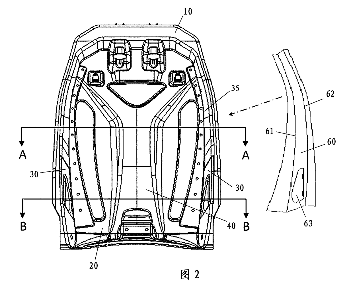
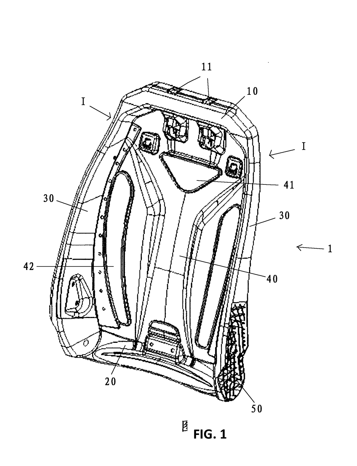
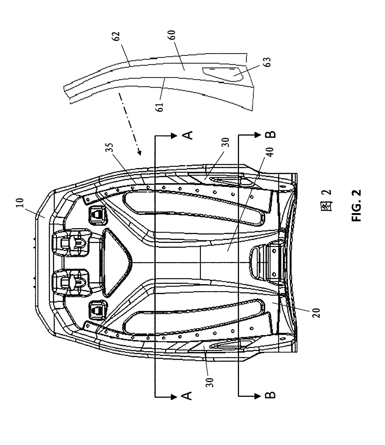
[0035]FIG. 1 is a perspective view showing an exemplary configuration of the seat backrest according to the invention. The seat backrest, as shown, is in an upright state, which is also the general use state when it is mounted in a vehicle (e.g. automobile). The seat backrest includes a framework 1 having an upper portion 10, a lower portion 20, a central support portion 40, left and right side portions 30 formed integrally as a piece by injection molding thermoplastic materials. The upper portion 10 and the lower portion 20 are generally horizontal, and the two side portions 30 are generally vertical and bilaterally symmetrical. The upper portion 10 is generally in the shape of an inverted U and the cross section thereof tapers towards tip ends of the U-shape. The two side portions 30, with the cross sections thereof generally tapering upwards, are joined integral...


PUM


Abstract

A seat backrest is provided, comprising a framework (1) including an upper portion (10), a lower portion (20), a central support portion (40) and two side portions (30) formed integrally by injection molding a thermoplastic material; and an elongated reinforcement (60) embedded in the side portion (30) and the central support portion (40) by overmolding and extending along the side portion (30), the reinforcement (60) being configured to bend along a boundary (35) between the side portion (30) and the central support portion (40). A seat including the backrest is also provided.

Description

TECHNICAL FIELD[0001]The present invention relates to a seat backrest used in particular in an automobile seat.BACKGROUND ART[0002]As one of the most important parts of a seat of a vehicle, in particular of an automobile, backrest is used for supporting the lumbar and back regions of an occupant and for absorbing impact forces applied by the occupant in particular in the event of a crash accident to provide sufficient cushion.[0003]A seat backrest mainly includes a framework and a cushion covering the framework. As a load supporting structure, the framework is traditionally made of a metallic material, such as carbon steel. However, the high density of the carbon steel is not good for reducing weight of the seat and the vehicle. Therefore, the use of carbon steel must be minimized to reduce weight, which limits the size and loading area of the backrest framework. For example, the lower portion and side portions of the backrest framework can only be formed into slats or bars having r...

Claims


Application Information

Patent Timeline
IPC IPC(8): B60N2/68B60N2/70
CPCB60N2/682B60N2/7029B60N2/686
Inventor SEO, HEE WONBAUMERT, MARTINCHENG, TSUNG-CHIEHJUN, SANGCHEOLLEE, DAEWOOKANG, SUNGHYUN
Owner BASF AG
Learn More