
Wearable electronic device

a wearable electronic and device technology, applied in the direction of elongated active element feed, resonant antenna, antenna earthing, etc., can solve the problems of difficult to implement an antenna in a compact device, harmful to human health, strong electromagnetic radiation, etc., and achieve the effect of more elastic space and more functional components

Active Publication Date: 2017-12-21
PEGATRON
View PDF4 Cites 13 Cited by
  • Summary
  • Abstract
  • Description
  • Claims
  • Application Information

AI Technical Summary

Benefits of technology

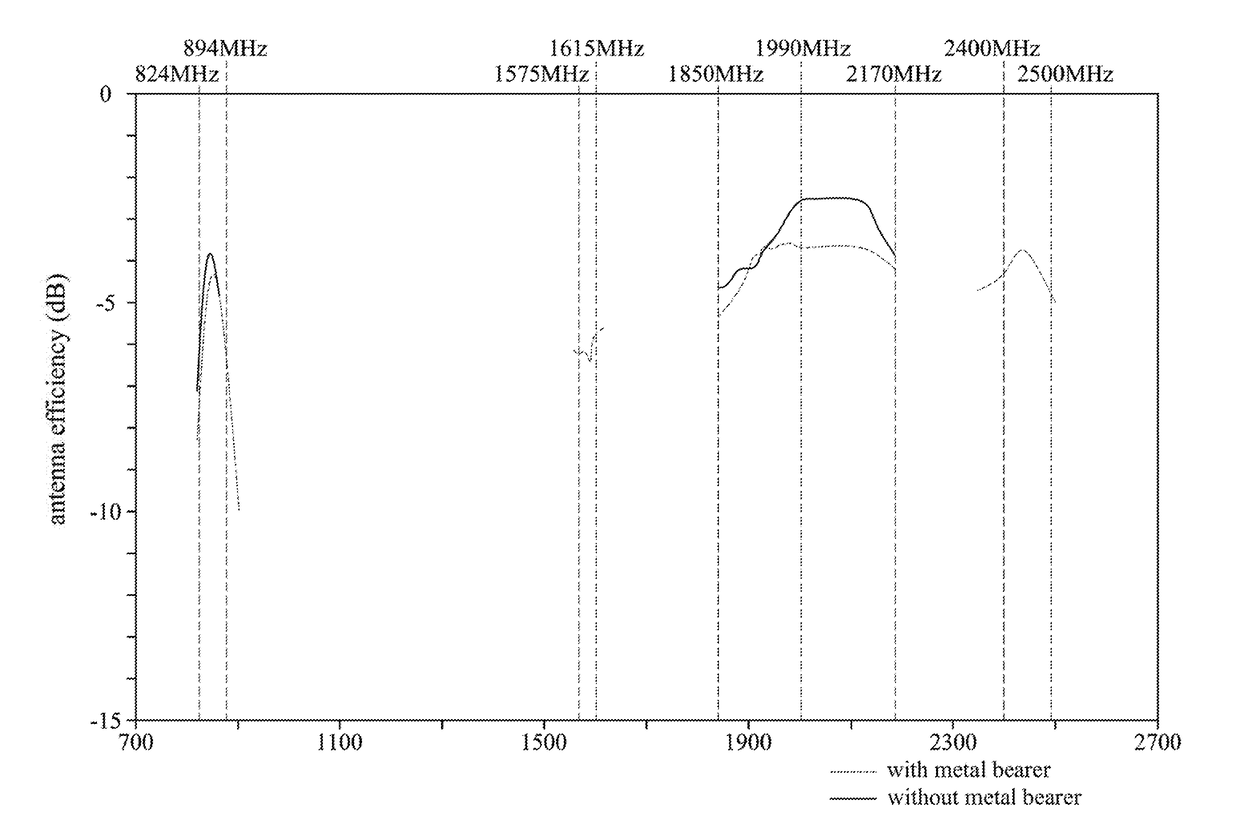
The patent describes a way to add an antenna to a wearable electronic device by putting it on the outside of the device's sidewall. This helps the device have more flexibility and space for other components, while also allowing it to have multiple antennas for different frequency ranges. As a result, it can be designed with a metal body while still meeting safety standards.

Problems solved by technology

However, it is not easy to implement an antenna in a compact device, such as a watch having a limited size.
On the other hand, strong electromagnetic radiation is harmful to human health, such that electronic products are usually governed by the Specific Absorption Rate (SAR) specifications of various countries.
It is an important issue for designers and researchers of the wearable device to fulfill the requirements of receiving and transmitting multiple frequency bands simultaneously on the single electronic product within a limited size and also to achieve a desirable appearance.

Method used


Image

  • Wearable electronic device
  • Wearable electronic device
  • Wearable electronic device

Examples


Embodiment Construction

[0018]Reference will now be made in detail to the present embodiments of the disclosure, examples of which are illustrated in the accompanying drawings. Wherever possible, the same reference numbers are used in the drawings and the description to refer to the same or like parts. Certain terms are used throughout the following description and claims, which refer to particular components. As one skilled in the art will appreciate, electronic equipment manufacturers may refer to a component by different names. This document does not intend to distinguish between components that differ in name but not in function. The disclosure can be more fully understood by reading the following detailed description of the embodiments, with reference made to the accompanying drawings; however, it is for illustrative purposes only and is not to restrict the present disclosure, nor to limit its operations. Any structures reassembled by the components and still have equal efficacy are within the scope o...


PUM


Abstract

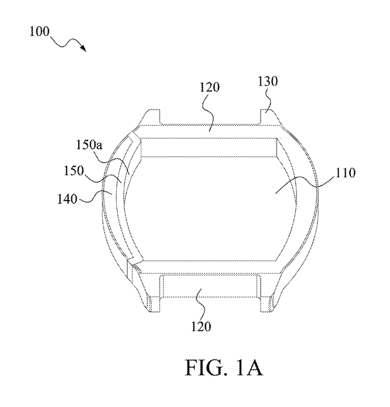
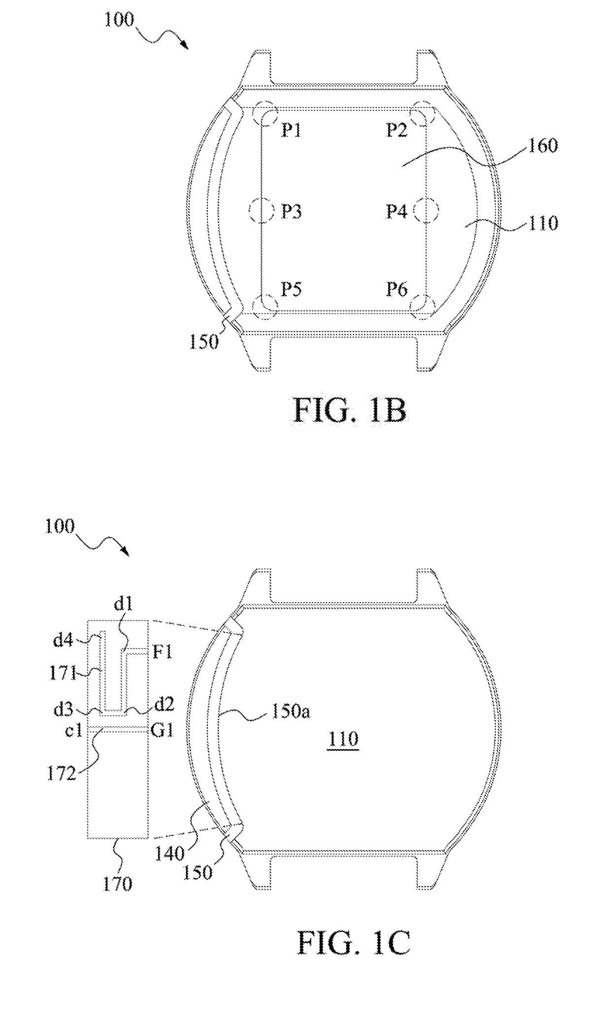
A wearable electronic device is disclosed. Wearable electronic device includes a casing, a dielectric component and an antenna wired circuit. The casing includes a metal bottom, a first metal sidewall connected to the metal bottom, a connection structure disposed at the first metal sidewall, and a second metal sidewall adjacent to the metal bottom and the first metal sidewall with a gap. The dielectric component is installed at the gap to electrically isolate the second metal sidewall from the first metal sidewall and the metal bottom. The antenna wired circuit is disposed at the dielectric component and electrically coupled to the second metal sidewall for resonating to generate a resonance band with the second metal sidewall.

Description

RELATED APPLICATION[0001]This application claims the priority benefit of Taiwan application serial no. 105118935, filed on Jun. 16, 2016, the entirety of which is herein incorporated by reference.BACKGROUNDField of Invention[0002]The present disclosure relates to a wearable electronic device. More particularly, the present disclosure relates to a wearable electronic device with a communication function.Description of Related Art[0003]Smart devices are one of the most popular products recently, and most people get used to the convenience provided by various smart devices in their daily life. In addition to smartphones and tablet PCs, wearable electronic devices such as smart watches and smart bracelets are modish and popular products on the market.[0004]Smart devices usually have wireless communication capabilities. A fast-paced development of smart devices also encourages new designs and developments of antennas on the smart devices. However, it is not easy to implement an antenna i...

Claims


Application Information

Patent Timeline
Patent Type & Authority Applications(United States)
IPC IPC(8): H01Q1/27H01Q5/30H01Q1/48H01Q1/52
CPCH01Q1/273H01Q1/48H01Q5/30H01Q1/521H01Q9/42
Inventor WU, CHIEN-YIWU, CHAO-HSUHUANG, SHIH-KENGLI, YA-JYUNCHANG, CHIA-CHI
Owner PEGATRON
Learn More