
ESD protection device and method

Active Publication Date: 2017-12-07
SEMICON MFG INT (SHANGHAI) CORP +1
View PDF2 Cites 4 Cited by
  • Summary
  • Abstract
  • Description
  • Claims
  • Application Information

AI Technical Summary

Benefits of technology

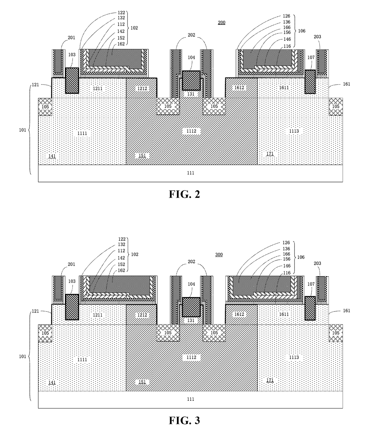
The present disclosure provides an electrostatic discharge (ESD) protection device that includes a substrate structure with a semiconductor substrate, a first fin, and a second fin on the semiconductor substrate. The device also includes a first gate structure on a surface portion of the first fin and a second region of the first fin, a first highly doped region in the first region of the first fin and a second region of the first fin, a second gate structure on a surface portion of the second region of the first fin, and a third highly doped region in the first region of the first fin. The device can provide effective protection against ESD events and can be used in various electronic devices.

Problems solved by technology

Semiconductor integrated circuits are subject to serious damage caused by ESD events.
However, for fin-type field effect transistor (FinFET) devices, the amount of generated hot carriers due to the small-size fin is insufficient to effectively trigger a GNNMOS transistor.

Method used


Image

  • ESD protection device and method
  • ESD protection device and method
  • ESD protection device and method

Examples


Embodiment Construction

[0031]In the following description, numerous specific details are provided for a thorough understanding of the present invention. However, it should be appreciated by those of skill in the art that the present invention may be realized without one or more of these details. In other examples, features and techniques known in the art will not be described for purposes of brevity.

[0032]It should be understood that the drawings are not drawn to scale, and similar reference numbers are used for representing similar elements. Embodiments of the invention are described herein with reference to perspective cross-section illustrations that are schematic illustrations of idealized embodiments (and intermediate structures) of the invention. The thickness of layers and regions in the drawings may be exaggerated relative to each other for clarity. Additionally, variations from the shapes of the illustrations as a result, for example, of manufacturing techniques and / or tolerances, are to be expec...


PUM


Abstract

An ESD protection device includes a substrate structure having a substrate, first and second fins, and first and second doped regions having different conductivity types. The first doped region includes a first portion of the substrate and a first region of the first fin, the second doped region includes a second portion of the substrate, a second region of the first fin adjacent to the first region and the second fin. The ESD device also includes a first gate structure on a surface portion of the first region and a surface portion of the second region of the first fin and including, from bottom to top, an interface layer on the surface portion of the first region and the surface portion of the second region of the first fin, a spacer, a high-k dielectric layer, a first work-function adjusting layer, a second work-function adjusting layer, and a gate.

Description

CROSS-REFERENCES TO RELATED APPLICATIONS[0001]This application claims priority to Chinese patent application No. 201610379423.8, filed on Jun. 1, 2016, the content of which is incorporated herein by reference in its entirety.FIELD OF THE INVENTION[0002]The present disclosure generally relates to semiconductor technology, and more particularly to electrostatic discharge (ESD) protection circuitry and semiconductor devices.BACKGROUND OF THE INVENTION[0003]Semiconductor integrated circuits are subject to serious damage caused by ESD events. As semiconductor features continue to decrease in sizes, supply voltages also continue to decrease. In relatively low power supply voltages (e.g., less than 6 V), shallow trench isolation (STI) diodes and gate-controlled diodes can be used as ESD protection devices. In relatively high power supply voltages (e.g., more than 6 V), gate-grounded N-type MOS (GGNMOS) transistors can be used as ESD protection devices.[0004]However, for fin-type field effe...

Claims


Application Information

Patent Timeline
IPC IPC(8): H01L27/02H01L29/66H01L29/49H01L29/08H01L29/16H01L21/8238H01L29/06H01L27/092H01L29/78H01L29/161
CPCH01L27/0274H01L27/0924H01L29/4966H01L29/0653H01L29/66545H01L29/161H01L29/7816H01L29/16H01L29/0847H01L21/823821H01L21/823842H01L21/823878H01L21/823814H01L29/1608H01L27/0251H01L27/0255H01L29/785H01L29/7391
Inventor LI, YONG
Owner SEMICON MFG INT (SHANGHAI) CORP
Learn More