
Method for correcting defective pixel artifacts in a direct radiography image

a technology of defective pixels and radiography, applied in the field of direct radiography, can solve the problems of defective pixels, unreliable sensor-pixels, non-representative image data, etc., and achieve the effect of reducing disturbing or missing image impact, improving workflow and visual inspection quality

Inactive Publication Date: 2017-11-30
AGFA NV
View PDF1 Cites 3 Cited by
  • Summary
  • Abstract
  • Description
  • Claims
  • Application Information

AI Technical Summary

Benefits of technology

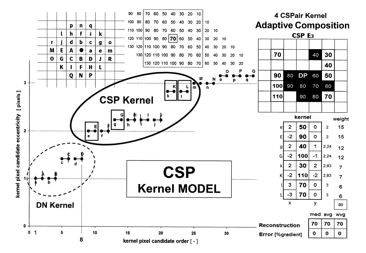
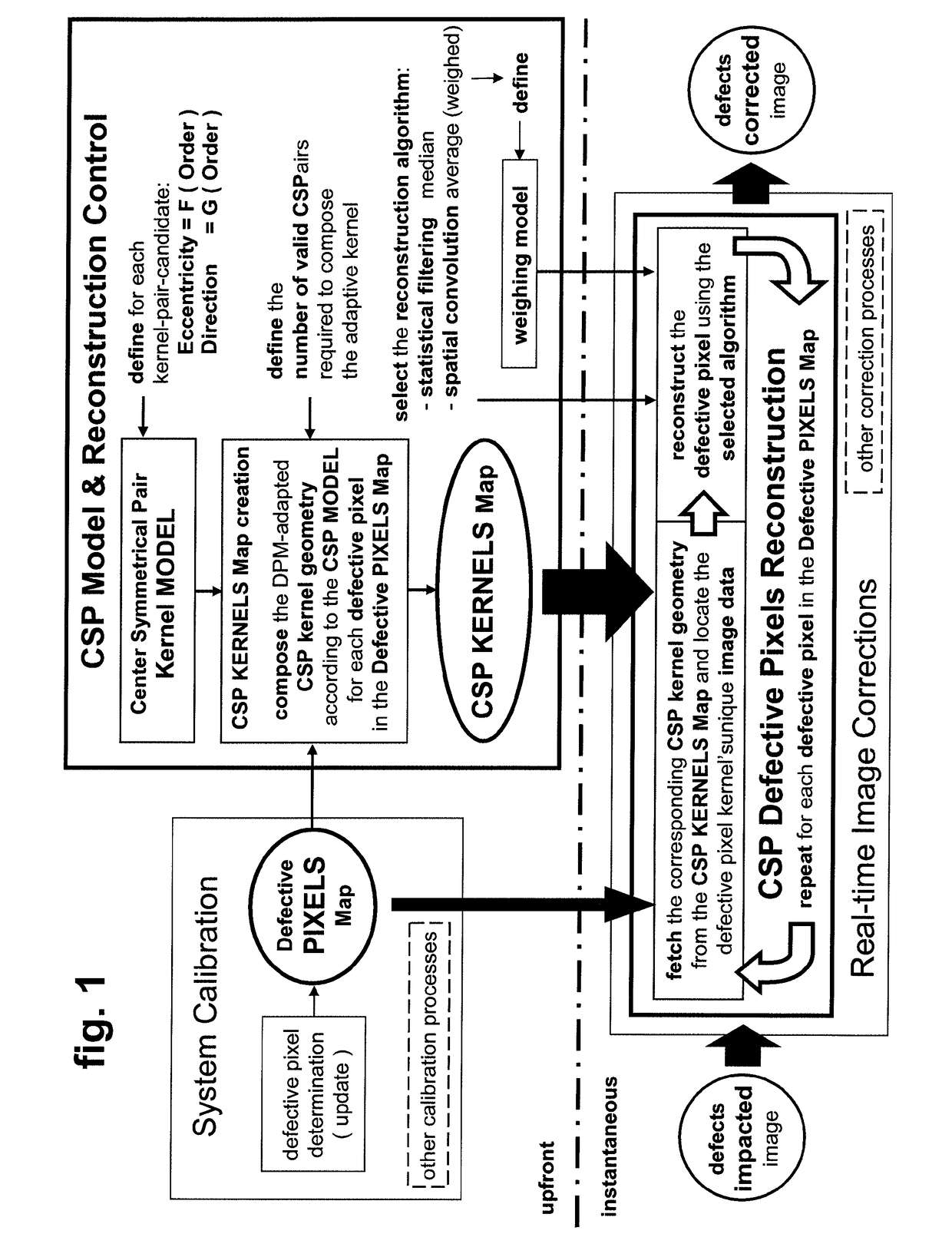
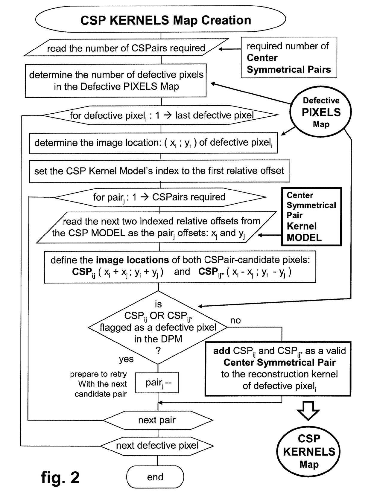
The invention is able to reconstruct defective pixel clusters in image-regions affected by signal gradients, in order to improve the quality of the visual inspection after diagnostic image acquisition. It creates an image-offset table for fast image-data access during real-time defective pixels reconstruction by merging the spatial data of the defective pixels with an adaptive center symmetrical pair kernel description. This results in a high quality reconstruction of defective flat panel detector pixel-clusters.

Problems solved by technology

Although these complex, solid state sensor based image-acquisition devices are calibrated on a regular basis to determine and compensate for the various sources of spread in the signal conversion characteristics of their sensor-pixels, array-wise arranged in the detector's sensitive entry-surface, some of these sensor-pixels are defective or behave irregular causing their image-data to be non-representative for the amount of light or x-rays they have been exposed to during signal integration.
The majority of these unreliable sensor-pixels, often referred to as defective pixels generating invalid image-data, are isolated pixels which are distributed across the surface of the array-sensor.
Even when the reconstruction value of that isolated pixel might slightly differ from its normal value, the image data generated at that specific image-location in case the sensor-pixel wouldn't have been defective, a small reconstruction error, the deviation between the replacement value and the normal value, still remains hardly detectable in the corrected image.
Even when a reconstruction value is calculated for each individual defective pixel in the cluster, the reconstruction requirements shouldn't be less severe than those applicable for the reconstruction of an isolated defective pixel because a group of clustered pixels exhibiting small reconstruction errors will more likely be regarded as an artificial and thus disturbing, visible image-artifact, revealing the cluster's inadequately hidden presence and size.
This phenomenon becomes even worse if the defective cluster is surrounded by image-data showing a signal-slope profile due to the presence of a local signal-gradient often induced by to the sudden, step-shaped contrast differences at the boundaries of radiographed objects with substantially different x-ray absorption properties like bone and soft tissue.
As a result the replacement value obtained for the defective pixel will generate a larger reconstruction error producing a local dented disturbance in the often fairly straight iso-contour lines thus making it even more difficult to hide the defective pixel cluster.

Method used


Image

  • Method for correcting defective pixel artifacts in a direct radiography image
  • Method for correcting defective pixel artifacts in a direct radiography image
  • Method for correcting defective pixel artifacts in a direct radiography image

Examples


Embodiment Construction

[0049]An x-ray or light sensitive array-sensor, a crucial opto-electronic component of each flat panel detector system, acts as a planar transducer which converts the spatial distribution of the time-integrated impinging x-ray radiation captured at pixel resolution into a set of digital data which can be exported as an uncorrected image.

[0050]To be able to do this the large-area array-sensor is often built up as a stack of contacting and or fused layers.

[0051]A scintillator material arranged at the radiation entry side of the detector is used as a first layer to convert impinging x-rays into emitted light.

[0052]The electronic array-layer consists of photo-sensitive pixel-elements like reverse biased PIN diodes which convert the locally impinging emitted light into electric charge carriers which can be captured during time integration and locally stored in the pixel as an x-ray exposure representative charge-package.

[0053]A third layer carries a vast array of electronic switches used...


PUM


Abstract

A method for reducing image disturbances caused by reconstructed defective pixel clusters located in signal-gradient affected diagnostic image regions. An individually adapted central symmetrical pair reconstruction (CSP) kernel is composed for a defective image pixel based on a kernel-pair candidate order encoded in a model thereby using the pixel's validity state. The image impacted by defective pixels is corrected in real-time by statistical filtering or spatial convolution of the kernel-associated image data accessible via a predetermined CSP kernels image-offsets structure.

Description

CROSS REFERENCE TO RELATED APPLICATIONS[0001]This application is a 371 National Stage Application of PCT / EP2015 / 079213, filed Dec. 10, 2015. This application claims the benefit of European Application No. 14197652.2, filed Dec. 12, 2014, which is incorporated by reference herein in its entirety.BACKGROUND OF THE INVENTION1. Field of the Invention[0002]The present invention relates to direct radiography. The invention more particularly relates to a method for correcting defective pixel image artifacts in such a way that the visibility of reconstructed defective pixel clusters located in image-regions with strong signal-gradients is significantly reduced.2. Description of the Related Art[0003]Static and dynamic flat panel detector based x-ray imaging systems are commonly used in various application areas ranging from non-destructive testing to medical diagnosis. Although these complex, solid state sensor based image-acquisition devices are calibrated on a regular basis to determine an...

Claims


Application Information

Patent Timeline
Patent Type & Authority Applications(United States)
IPC IPC(8): G06T5/00
CPCG06T5/005G06T2207/10116G06T2207/20028G06T2207/20032G06T2207/20012G06T5/77
Inventor CRESENS, MARCVAN GOUBERGEN, HERMAN
Owner AGFA NV
Learn More