


Quick Research
Generate reliable direction feasibility study reports for your R&D in just a few steps.

Technical Q&A
Discover and master advanced knowledge NOW. Basics, ideas, possibilities, all at once.

Find Solutions
As an expert in R&D theories, this can generate solutions to your technical problems instantly.

Evaluate Feasibility
Analyze your overall solution with one click, know your potential R&D risks in advance.

Monitor Landscape
Get weekly tech updates, stay abreast of the latest tech innovations and key insights.
Pulse radar, method of correcting transmission pulse in pulse radar, and method of correcting reception pulse in pulse radar
a technology of pulse radar and transmission pulse, which is applied in the field of pulse radar, can solve problems such as increasing circuit complexity, and achieve the effect of reducing waveform degradation and reducing sensing performan
- Summary
- Abstract
- Description
- Claims
- Application Information
AI Technical Summary
Benefits of technology
Problems solved by technology
Method used
Image


Examples
first embodiment
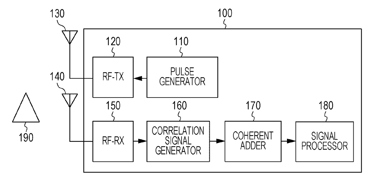
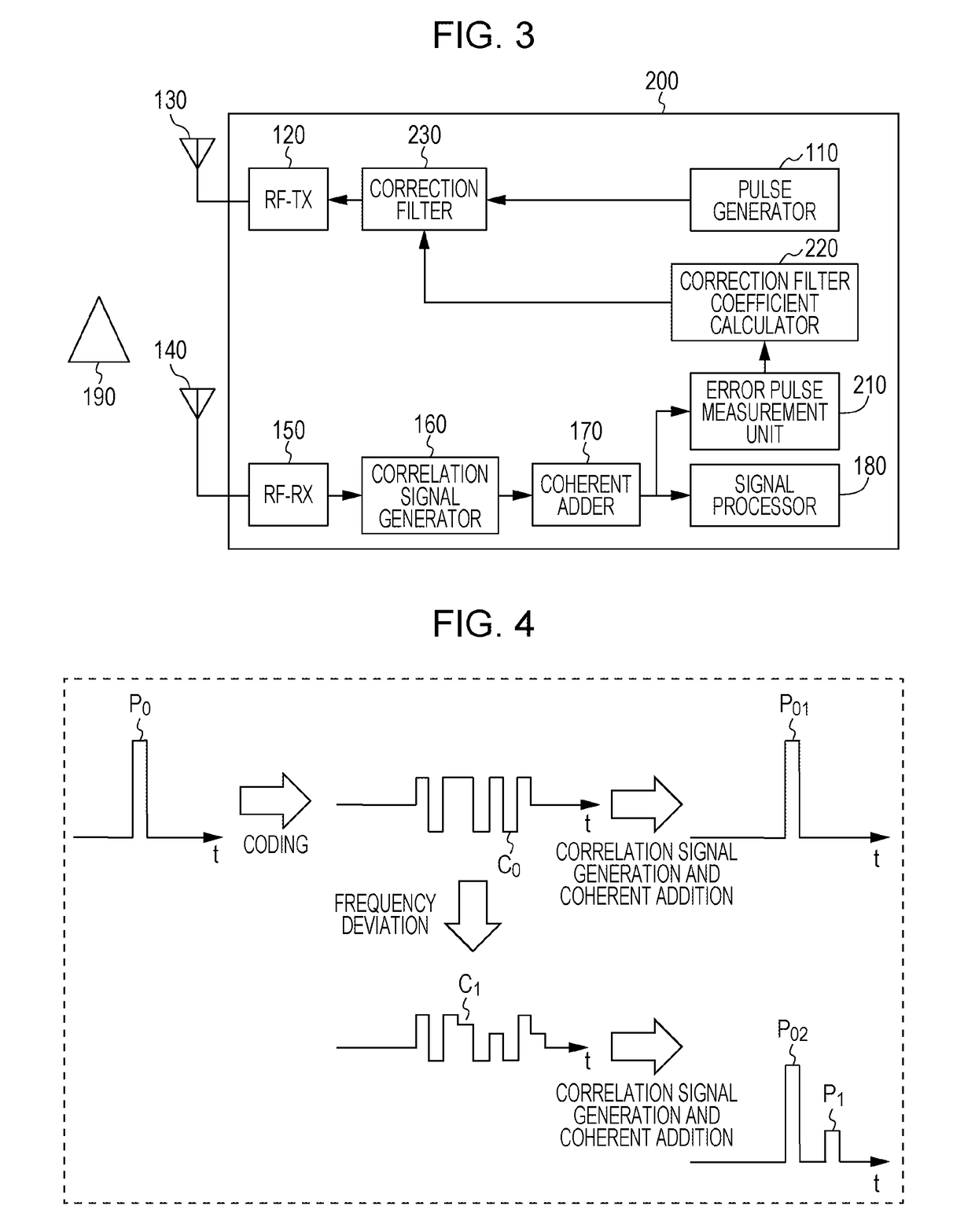
[0028]FIG. 3 illustrates an example of a configuration of a pulse radar 200 according to a first embodiment. The pulse radar 200 includes a transmission unit including a pulse generator 110, a correction filter 230, a radio frequency (RF) transmitter 120, and a transmission antenna 130. The pulse radar 200 also includes a reception unit including a reception antenna 140, a radio frequency (RF) receiver 150, a correlation signal generator 160, a coherent adder 170, a signal processor 180, an error pulse measurement unit 210, and a correction filter coefficient calculator 220. Note that in the configuration of the pulse radar 200, the correction filter 230, the error pulse measurement unit 210, and the correction filter coefficient calculator 220 are elements that the pulse radar 200 further includes in addition to the elements of the pulse radar 100 shown in FIG. 1. In FIG. 3, a corner reflector 190 is disposed separately from the pulse radar 200.
[0029]The correction filter 230 corre...
second embodiment
[0054]FIG. 8 is a diagram illustrating an example of error pulses according to a second embodiment. In the first embodiment described above, it is assumed that an error pulse occurs in a range of location corresponding to about one sampling period. In the second embodiment, in contrast, it is assumed that error pulses occur in a range of location corresponding to several sampling periods. In the following description, it is assumed that error pulses with high power levels occur in a range of location corresponding to several sampling periods.
[0055]In FIG. 8, error pulses (error pulses P4 to P6) having high power levels associated with the main pulse (the first pulse P01) at time t0 occur across three sampling periods from t4 to t6. In the example shown in FIG. 8, three error pulses P4 to P6 are error pulses to be corrected.
[0056]More specifically, the error pulse measurement unit 210 first identifies an error pulse P5 with a highest power level of all error pulses. Subsequently, the...
third embodiment
[0060]FIG. 9 is a diagram illustrating an example of a configuration of a pulse radar 300 according to a third embodiment. The pulse radar 300 includes a transmission unit including a pulse generator 110, a radio frequency transmitter 120, and a transmission antenna 130. The pulse radar 300 further includes a reception unit including a reception antenna 140, a radio frequency receiver 150, a correction filter 231, a correlation signal generator 160, a coherent adder 170, a signal processor 180, an error pulse measurement unit 210, and a correction filter coefficient calculator 220.
[0061]The pulse radar 300 according to the third embodiment is different from the pulse radar 200 according to the first embodiment in terms of an input signal given to the correction filter and a unit to which an output signal from the correction filter is input. The correction filter 230 of the pulse radar 200 receives input signals from the pulse generator 110 and the correction filter coefficient calcu...
PUM
 Abstract
Description
Claims
Application Information
 - R&D Engineer
- R&D Manager
- IP Professional
- Industry Leading Data Capabilities
- Powerful AI technology
- Patent DNA Extraction
Browse by: Latest US Patents, China's latest patents, Technical Efficacy Thesaurus, Application Domain, Technology Topic, Popular Technical Reports.
© 2024 PatSnap. All rights reserved.Legal|Privacy policy|Modern Slavery Act Transparency Statement|Sitemap|About US| Contact US: help@patsnap.com