
Signal Processing Apparatus and Method

a technology of signal processing and processing apparatus, applied in the direction of digital transmission, transmission path sub-channel allocation, wireless communication, etc., can solve the problems of insufficient memory at an acceptable cost, inability to decode received data, and inability to provide on-chip sram with enough memory, etc., to and improve the reliability of decoding received data bits

Active Publication Date: 2017-11-16
TELEFON AB LM ERICSSON (PUBL)
View PDF6 Cites 5 Cited by
  • Summary
  • Abstract
  • Description
  • Claims
  • Application Information

AI Technical Summary

Benefits of technology

The patent text is about a system and method that takes into account leakage from a storage device when using a stored soft data bit for decoding data bits. This improves the reliability of decoding and reduces power consumption and latency. The system also utilizes a transport block that contains a code word and another code word to improve system efficiency.

Problems solved by technology

When transmitting data over wireless channels, errors will be introduced due to, for example, variations in the received signal quality.
This means that an incorrectly received transport block needs to be stored in a buffer at the receiving equipment until the retransmitted transport block arrives.
On-chip SRAM is fast, but is also typically small and expensive.
So, for bad wireless channel conditions, where a lot of HARQ buffer memory is needed, on-chip SRAM might not provide enough memory at an acceptable cost.
As time passes, the charge in the capacitor leaks away.
Each refresh will consume energy.
The refreshing also interferes with memory access, because no data can be transferred to or from the memory while the memory is being refreshed, thereby increasing latency.
Moreover, the delay may be longer for networks operating in a time division duplex (TDD) mode, rather than a frequency division duplex (FDD) mode, due to the separation in the time domain of uplink and downlink time slots.

Method used


Image

  • Signal Processing Apparatus and Method
  • Signal Processing Apparatus and Method
  • Signal Processing Apparatus and Method

Examples


Embodiment Construction

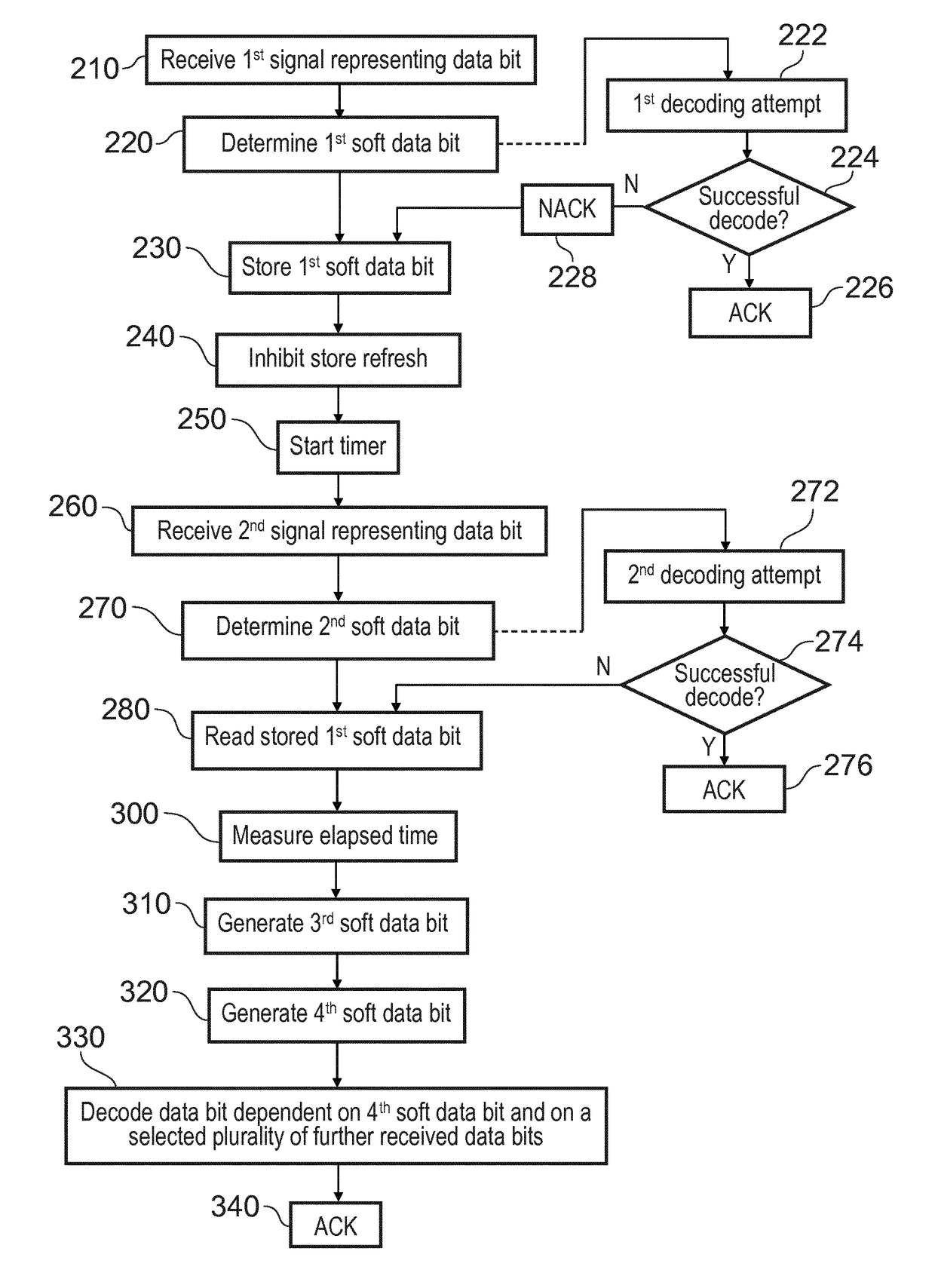
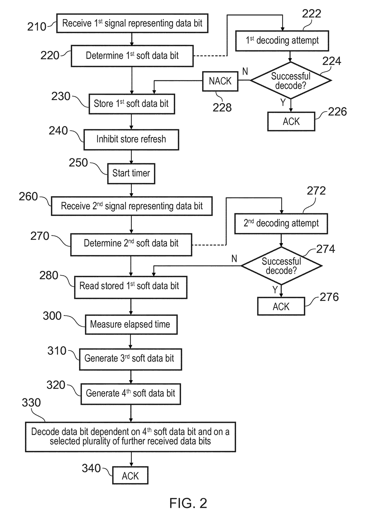
[0008]According to a first aspect there is provided a method of operating a signal processing apparatus, comprising:

[0009]receiving a first signal representing a received data bit;

[0010]determining from the first signal a first soft data bit;

[0011]storing the first soft data bit in a leaky storage device;

[0012]receiving a second signal representing the received data bit;

[0013]determining from the second signal a second soft data bit;

[0014]reading from the leaky storage device the stored first soft data bit;

[0015]measuring an elapsed leakage time of the stored first soft data bit;

[0016]generating a third soft data bit dependent on the stored first soft data bit read from the leaky storage device and on the elapsed leakage time;

[0017]generating a fourth soft data bit by combining the second soft data bit and the third soft data bit;

[0018]decoding the received data bit dependent on the fourth soft data bit and on a selected plurality of further received data bits.

[0019]According to a s...


PUM


Abstract

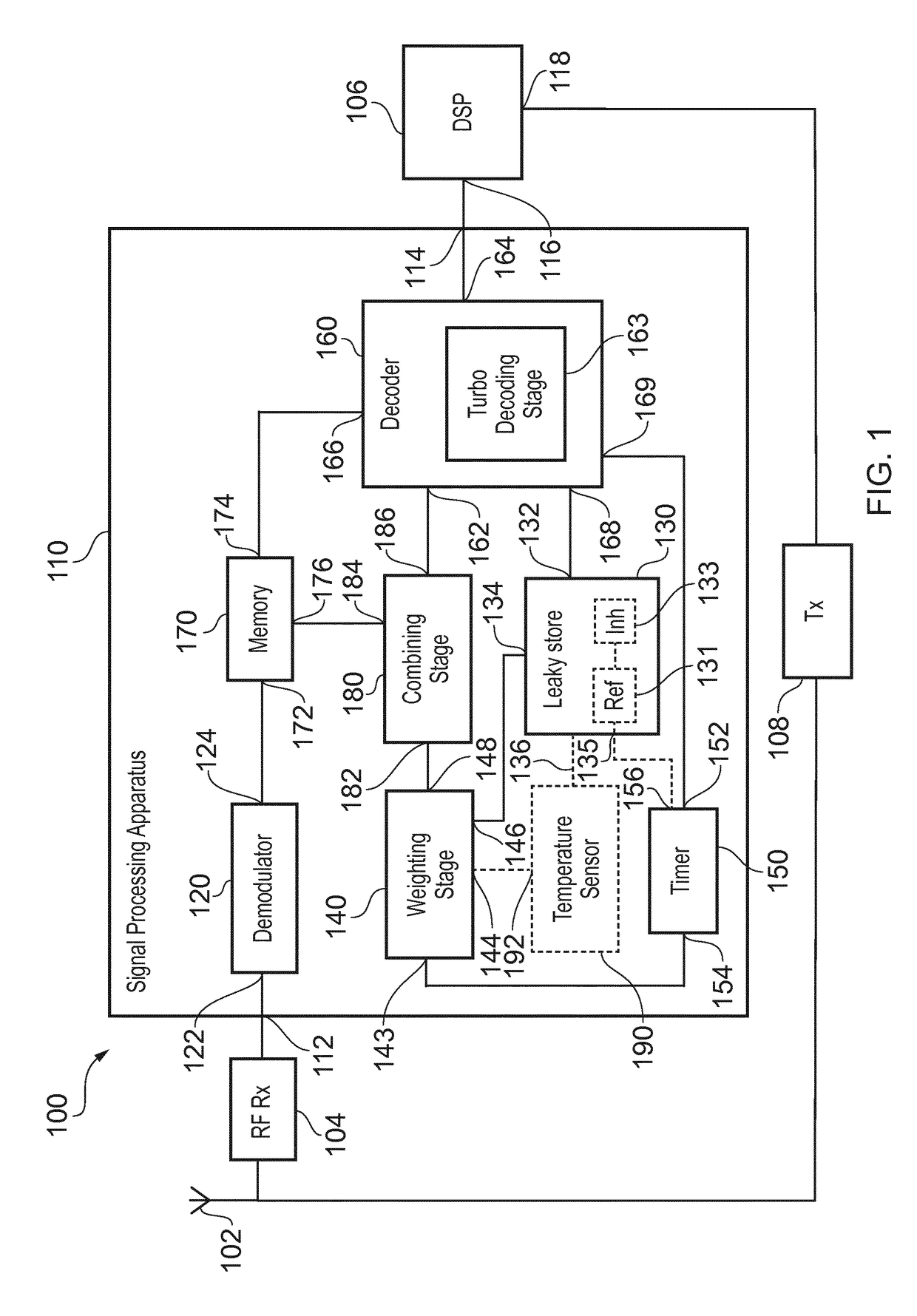
A method of operating a signal processing apparatus (110) comprises receiving a first signal representing a received data bit, determining from the first signal a first soft data bit, storing the first soft data bit in a leaky storage device (130), receiving a second signal representing the received data bit, and determining from the second signal a second soft data bit. The stored first soft data bit is read from the leaky storage device (130), an elapsed leakage time of the stored first soft data bit is measured, and a third soft data bit is generated dependent on the stored first soft data bit read from the leaky storage device (130) and on the elapsed leakage time. A fourth soft data bit is generated by combining the second soft data bit and the third soft data bit, and the received data bit is decoded dependent on the fourth soft data bit and on a selected plurality of further received data bits.

Description

FIELD OF THE DISCLOSURE[0001]The present disclosure relates to a signal processing apparatus, a mobile communication device comprising the signal processing apparatus, and a method of operating a signal processing apparatus.BACKGROUND TO THE DISCLOSURE[0002]When transmitting data over wireless channels, errors will be introduced due to, for example, variations in the received signal quality. Wireless modems typically use forward error correction (FEC), where redundancy is incorporated in the transmitted signal by including parity bits calculated from the transmitted information bits according to a coding scheme. Therefore, the number of bits transmitted over the channel is larger than the number of information bits.[0003]Another way to protect against transmission errors is to use an automatic repeat request (ARQ) scheme in which a receiver uses an error detection code, such as a cyclic redundancy check (CRC), to detect if a data packet is received correctly or not. If no error is d...

Claims


Application Information

Patent Timeline
Patent Type & Authority Applications(United States)
IPC IPC(8): H04L1/00H04L1/18H04W28/04H04L5/00
CPCH04L1/0052H04L1/1816H04L1/1845H04W28/04H04L5/0055H04L1/0045
Inventor ANYURU, ANDREASUGGMARK, JOHAN GEORG MICHAEL
Owner TELEFON AB LM ERICSSON (PUBL)
Learn More