Endoscope

Active Publication Date: 2017-10-26
PANASONIC I PRO SENSING SOLUTIONS CO LTD
View PDF6 Cites 8 Cited by
  • Summary
  • Abstract
  • Description
  • Claims
  • Application Information

AI Technical Summary

Benefits of technology

The present disclosure aims to provide an endoscope that can prevent stray light from the lighting member and securely fix the lens and imaging element in place while also reducing the size of the endoscope. It does this by improving space efficiency and reducing useless space in the insertion tip surface. This results in a more efficient and effective endoscope for use in medical procedures.

Problems solved by technology

The configuration in which the lighting member is placed around the circular lens results in a useless space in an insertion tip surface.
In other words, a low level of space efficiency arises, which results in disadvantages in terms of endoscope size reduction.
In addition, it is difficult to stably fix the circular lens and a quadrangular imaging element.
Furthermore, it is difficult to reduce the size of the light guide fiber bundle 509 because the light guide fiber bundle 509 is obtained by multiple bare fiber strands being bundled up by being hardened by a low-viscosity adhesive and, as such, the area of its outer periphery increases and leaking light is likely to move into the imaging element.
This leaking light becomes stray light in the optical system that leads to image quality deterioration.

Method used


Image

  • Endoscope
  • Endoscope
  • Endoscope

Examples


first configuration example

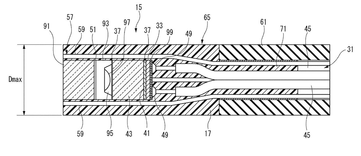
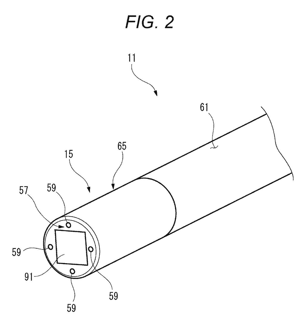
[0069]FIG. 2 is a perspective view illustrating an appearance of the tip portion 15 of the endoscope 11 according to the present embodiment that is seen from a front side. FIG. 3 is a sectional view illustrating a configuration example of the tip portion 15 of the endoscope 11 according to the present embodiment. In the endoscope 11 illustrated in FIG. 2, the maximum outer diameter Dmax of the tip portion 15 illustrated in FIG. 3 can be formed to have a range of a finite diameter to 1.0 mm, which is equivalent to the diameter of a circle circumscribed about a substrate of the imaging element 33 that can be diced.

[0070]In the endoscope 11 according to the present embodiment, an imaging element that has one side having a dimension of 0.5 mm or less is used as the imaging element 33 that has a square cross section in a direction perpendicular to the direction of an optical axis or an axial direction through a center of a lens (a center axis of the lens). Accordingly, the imaging elemen...

second configuration example

[0072]In the endoscope 11 according to the present embodiment, the endoscope 11 according to the second configuration example has the substrate of the imaging element 33 formed in a square shape and conductor connection portions 49 placed at four corners of the substrate of the imaging element 33 as illustrated in FIG. 5. One of the conductor connection portions 49 is formed in, for example, a circular shape. The four conductor connection portions 49 are placed at the four square corners. As a result, the four conductor connection portions 49 can be placed with a maximum distance of separation from one another.

[0073]In the transmission cable 31, conductors of respective electric power and signal lines that are electric wires 45 are covered by insulating coatings. The four electric wires 45 are placed in two, upper and lower, layers with two of the four on the left and the other two on the right. Outer peripheries of the insulating coatings are bundled up by an outer covering, which ...

third configuration example

[0075]FIG. 4 is a sectional view illustrating a configuration example of a state where a lens 93 and the imaging element 33 of the endoscope 11 according to the present embodiment are attached via an adhesive resin 37. As illustrated in FIG. 4, the endoscope 11 according to the third configuration example is provided with an objective cover glass 91, an element cover glass 43, the imaging element 33 where an imaging surface 41 is covered by the element cover glass 43, the lens 93 pinched between the objective cover glass 91 and the element cover glass 43 with its optical axis corresponding to the center of the imaging surface 41, an aperture 51 disposed between the objective cover glass 91 and the lens 93, the adhesive resin 37 fixing the lens 93 and the element cover glass 43, and an air layer 95 disposed between the lens 93 and the element cover glass 43.

[0076]A small charge coupled device (CCD) or complementary metal-oxide semiconductor (CMOS) imaging device that has a square sha...


PUM


Abstract

A lens having a quadrangular outer shape in a direction perpendicular to its center, an imaging element having a quadrangular outer shape in the direction perpendicular to the center axis, an element cover glass covering an imaging surface of the imaging element, a light guide placed outside at least one side of the lens and extending along the center axis, and a cylinder holder disposed between the lens and the light guide are disposed in a tip portion of an endoscope.

Description

CROSS REFERENCE TO RELATED APPLICATIONS[0001]This application is based on Japanese Patent Applications (Nos. 2016-087491, 2016-087488, 2016-087487) filed on Apr. 25, 2016, the contents of which are incorporated herein by reference.BACKGROUND OF THE INVENTION1. Field of the Invention[0002]The present disclosure relates to an endoscope.2. Description of the Related Art[0003]In the related art, a small-diameter endoscope that has a diameter of less than 3 mm is known as illustrated in FIGS. 46 and 47 (refer to, for example, JP-A-2008-212309). FIG. 46 is a front view of a tip portion of a small-diameter electronic endoscope according to the related art. FIG. 47 is a perspective view of a light guide fiber bundle unit in the tip portion of the small-diameter electronic endoscope. In the small-diameter endoscope according to JP-A-2008-212309, an outer periphery of an observation window 501 is fitted into an insulating tube 503 and a tip portion main body inner tube 505 is placed on an out...

Claims


Application Information

Patent Timeline
IPC IPC(8): G02B23/24H04N5/225A61B1/00A61B1/06A61B1/04G02B7/02
CPCG02B23/2469H04N5/2256G02B23/243G02B7/02H04N2005/2255A61B1/06A61B1/00009A61B1/04A61B1/00137G02B23/2484G02B23/2423A61B1/05G02B7/022A61B1/0676H04N23/51H04N23/56H04N23/57H04N23/555H04N23/55A61B2562/18A61B2562/185A61B1/0661A61B1/0684A61B1/0692
Inventor HATASE, YUICHIHARAGUCHI, NAOYUKIMIYANISHI, SATORUSANADA, TAKAFUMI
Owner PANASONIC I PRO SENSING SOLUTIONS CO LTD
Why Eureka
Try Eureka