
Systems and methods for magnetic resonance thermometry using balanced steady state free precession

a steady state free, balanced technology, applied in the field of magnetic resonance thermometry using balanced steady state free precession, can solve the problems of unsatisfactory effect, unsatisfactory detection and quantification of small and/or fast temperature changes, and unsatisfactory effect, and achieve the effect of accurate measurement and greater sensitivity and speed

Active Publication Date: 2017-10-05
UNIV OF VIRGINIA ALUMNI PATENTS FOUND
View PDF0 Cites 2 Cited by
  • Summary
  • Abstract
  • Description
  • Claims
  • Application Information

AI Technical Summary

Benefits of technology

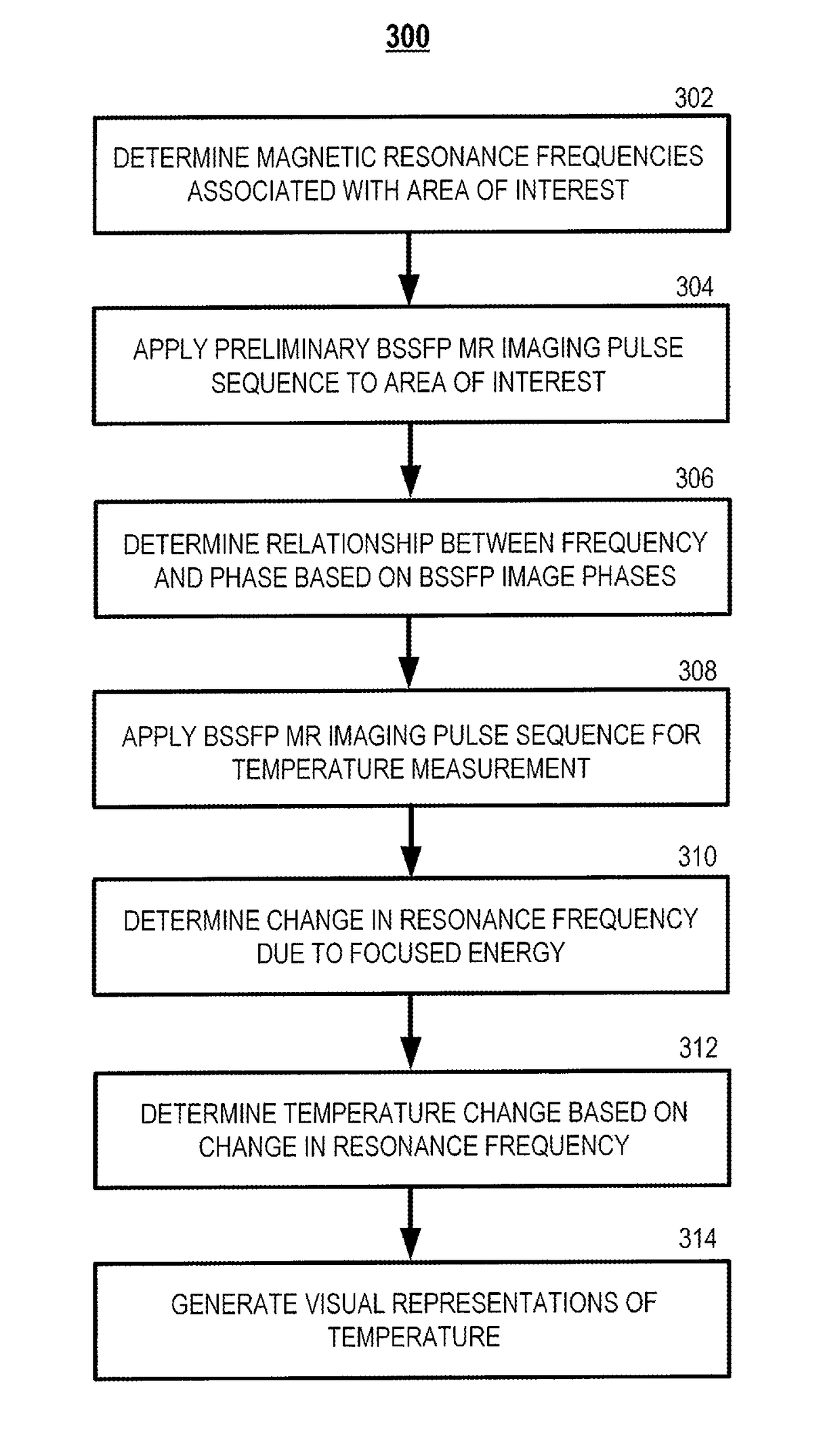
The present patent is about a system and method for accurately measuring temperature changes in aqueous media using magnetic resonance imaging. The method utilizes a balanced steady state free precession (bSSFP) pulse sequence and a PRF-based thermometry technique. This allows for the mapping of temperature changes over time in small, fast changes over a limited spatial extent, which is commonly encountered during focused ultrasound procedures. Additionally, the method includes a feedback loop that can dynamically adjust the central frequency of the sensitivity window in response to measured temperature changes, resulting in the expansion of the range of temperature changes that can be accurately measured. The technical effect of the patent is greater sensitivity and speed for MR thermometry and thermography, providing valuable information for focused ultrasound procedures and other medical applications.

Problems solved by technology

Focused ultrasound is also used for non-ablative interventions, in which tissue heating is possible but is not the desired effect.
Although some of these prior methods for MR thermometry have been applied in various contexts, including focused ultrasound, they are not ideal for detecting and quantifying small and / or fast temperature changes due to limited sensitivity and / or speed.
However, in practice, TE is limited by T2* relaxation.
That is, increasing sensitivity by increasing TE reduces the achievable temporal resolution of the temperature measurements.
Accordingly, there are practical limits to the sensitivity and speed achievable with MR thermometry using a spoiled GRE pulse sequence.
The achievable temporal resolution of the technique of [4] is not ideal as multiple image acquisitions must be woven into each PRF shift measurement.

Method used


Image

  • Systems and methods for magnetic resonance thermometry using balanced steady state free precession
  • Systems and methods for magnetic resonance thermometry using balanced steady state free precession
  • Systems and methods for magnetic resonance thermometry using balanced steady state free precession

Examples


example implementations

AND RESULTS

[0101]Various aspects of the present disclosure may be still more fully understood from the following description of some example implementations and corresponding results and the images of FIGS. 7-12. Some experimental data are presented herein for purposes of illustration and should not be construed as limiting the scope of the present disclosure in any way or excluding any alternative or additional embodiments.

example 1

[0102]A first example (hereinafter referred to as “Example 1”) of practicing aspects of the present disclosure will now be described along with corresponding results and with reference to illustrations in FIGS. 7-9.

[0103]Experiments were performed in a gel phantom using an MR-compatible 1 MHz FUS system with integrated RF coil (RK-100, FUS Instruments Inc., Toronto) and 3T MR whole-body scanner (Siemens Trio). To demonstrate that bSSFP thermometry can deliver quantitative accuracy similar to the conventional GRE method, both pulse sequences were used to monitor focal heating during a 10 s, 4 W sonication. The GRE pulse sequence parameters (TR / TE=17 / 9 ms with a FA=15°) provided a temporal resolution of 1 s, whereas the bSSFP pulse sequence parameters (TR / TE=4 / 2 ms with a FA=4°) provided a temporal resolution of 0.24 s. FIG. 7 shows the measured temperature evolution at the center of the focal spot for 10 s sonication at 4 W. The bSSFP acquisition has four times better temporal resolu...

example 2

[0105]A second example (hereinafter referred to as “Example 2”) of practicing aspects of the present disclosure will now be described along with corresponding results and with reference to illustrations in FIGS. 10-12.

[0106]For a bSSFP pulse sequence without phase cycling, the theoretical image phase at TE=TR / 2 is

=tan−1((E2 sin β)(1−E2 cos β))+β / 2  [Eq. 6]

where E2=e−TR / T2, β=2πΔfTR, and Δf is the difference between the true resonance frequency and the operating frequency, often referred to as the off-resonance frequency. The bSSFP image phase undergoes an abrupt transition near resonance (Δf=0 Hz) (see FIG. 11). The on-resonance phase slope is (d) / (d(Δf))=2πT2, resulting in higher sensitivity than the GRE method, which has a TE-dependent phase slope of 2πTE. Although the bSSFP phase behavior is nonlinear in the Δf and depends on the properties of the tissue (namely T2), its functional form can be measured by acquiring a series of bSSFP images with different effective frequency off...


PUM


Abstract

Some aspects of the present disclosure relate to systems and methods for magnetic resonance thermometry. In one embodiment, a preliminary balanced steady state free precession (bSSFP) magnetic resonance imaging pulse sequence is applied to an area of interest of a subject. Based on bSSFP image phases, a relationship between frequency and image phase associated with the area of interest can be determined and a bSSFP magnetic resonance imaging pulse sequence applied for temperature change measurement during and / or after focused energy is applied to the subject. Based on image phase change associated with temperature change and using the determined relationship between frequency and image phase, a change in the resonance frequency associated with the target area due to the application of the focused energy can be determined, and the temperature change can be determined based on the determined change in the resonance frequency.

Description

CROSS-REFERENCE TO RELATED APPLICATION[0001]This application claims priority to and benefit under 35 U.S.C §119(e) of U.S. Provisional Patent Application Ser. No. 62 / 062,872 filed Oct. 11, 2014, which is hereby incorporated by reference herein in its entirety as if fully set forth below.[0002]Some references, which include various publications, are cited in a reference list and discussed in the disclosure provided herein. The citation and / or discussion of such references is provided merely to clarify the description of the present disclosure and is not an admission that any such reference is “prior art” to any aspects of the present disclosure described herein. In terms of notation, “[n]” corresponds to the nth reference in the list. All references cited and discussed in this specification are incorporated herein by reference in their entireties and to the same extent as if each reference was individually incorporated by reference.BACKGROUND[0003]Magnetic resonance imaging (MRI) has...

Claims


Application Information

Patent Timeline
Patent Type & Authority Applications(United States)
IPC IPC(8): G01R33/48A61B5/01G01R33/561
CPCG01R33/4804A61B5/055A61B5/015G01R33/5614A61B5/4836A61B5/0036
Inventor MILLER, GRADY WILSONZHENG, YUAN
Owner UNIV OF VIRGINIA ALUMNI PATENTS FOUND
Learn More