
Radio access node, communication terminal and methods performed therein

Inactive Publication Date: 2017-09-28
TELEFON AB LM ERICSSON (PUBL)
View PDF8 Cites 24 Cited by
  • Summary
  • Abstract
  • Description
  • Claims
  • Application Information

AI Technical Summary

Benefits of technology

The patent text describes a mechanism to improve the performance of a wireless network using telecommunication technology in an unlicensed spectrum. The mechanism involves using a radio access node that can start transmission at different positions within a subframe. This allows the network to efficiently use resources and improve performance, even when part of the transmission has to stop due to the need for LBT.

Problems solved by technology

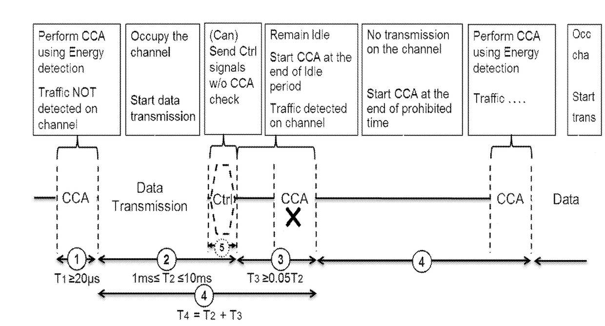
Regulatory requirements, however, may not permit transmissions in the unlicensed spectrum without prior channel sensing.
This scheme does not allow a wireless medium to be reserved at specific instances of time.
However, for the DL the radio access node is unable to measure any channel parameters.
Effectively, this means that if several radio access nodes are within range, they will have to share the channel in time, and the throughput for the individual radio access nodes may be severely degraded.
However, the spectrum allocated to LTE is limited which cannot meet the ever increasing demand for larger throughput from applications / services.
Operating LTE in the same manner in unlicensed spectrum as in licensed spectrum can seriously degrade the performance of Wi-Fi as Wi-Fi will not transmit once it detects that the channel is occupied.
It is thus a problem how the communication terminal will know whether the radio access node is performing LBT or not, since it impacts the mapping of EPDCCH and PDSCH modulated symbols to resource elements.
This would result in a decoding failure and unnecessary power consumption at the communication terminal and inefficient transmission at the radio access node.
This will lead to a limited performance of the wireless communications network.

Method used


Image

  • Radio access node, communication terminal and methods performed therein
  • Radio access node, communication terminal and methods performed therein
  • Radio access node, communication terminal and methods performed therein

Examples


Embodiment Construction

[0056]Embodiments herein relate to wireless communication networks in general. FIG. 7a is a schematic overview depicting a wireless communication network 1. The wireless communication network 1 comprises one or more RANs and one or more CNs. The wireless communication network 1 may use a number of different technologies, such as Long Term Evolution (LTE), LTE-Advanced, Wideband Code Division Multiple Access (WCDMA), Global System for Mobile communications / Enhanced Data rate for GSM Evolution (GSM / EDGE), Worldwide Interoperability for Microwave Access (WiMax), or Ultra Mobile Broadband (UMB), just to mention a few possible implementations. The wireless communication network 1 is exemplified herein as an LTE network.

[0057]In the wireless communication network 1, a communication terminal 10, also known as a wireless device, a user equipment and / or a wireless terminal, communicates via a Radio Access Network (RAN) to one or more core networks (CN). It should be understood by the skilled...


PUM


Abstract

A radio access node serves the communication terminal in at least one of a first cell on a carrier of a licensed or unlicensed spectrum, and / or a second cell on a carrier of an unlicensed spectrum. The radio access node determines whether a Listen Before Talk, LBT, process is to be performed or not in the second cell. The radio access node schedules, based on whether the LBT process is to be performed in a subframe on the second cell or not, a control channel and / or a data channel with a start position in the subframe out of at least two start positions. The radio access node transmits control information on the control channel and / or data on the data channel as scheduled to the communication terminal.

Description

TECHNICAL FIELD[0001]Embodiments herein relate to a radio access node, a communication terminal and methods performed therein. In particular embodiments herein relate to scheduling a control channel and / or a data channel to a communication terminal.BACKGROUND[0002]In a typical wireless communication network, communication terminals, also known as wireless devices and / or user equipments (UEs), communicate via a Radio Access Network (RAN) to one or more core networks. The RAN covers a geographical area which is divided into cell areas, with each cell area being served by a radio access node such as a base station, e.g., a radio base station (RBS), which in some networks may also be called, for example, a “NodeB” or “eNodeB”. A cell is a geographical area where radio coverage is provided by the radio base station at a base station site or an antenna site in case the antenna and the radio base station are not co-located. Each cell is identified by an identity within the local radio area...

Claims


Application Information

Patent Timeline
IPC IPC(8): H04W74/08H04W24/08H04W72/12H04W72/04H04W48/16H04W28/18H04W16/14H04W48/08
CPCH04W74/0808H04W16/14H04W24/08H04W72/1278H04W72/0446H04W48/16H04W28/18H04W48/08H04L5/001H04L5/005H04L5/0053H04L5/0094H04W72/20
Inventor FRENNE, MATTIASCHENG, JUNG-FULARSSON, DANIELKOORAPATY, HAVISHFALAHATI, SOROUR
Owner TELEFON AB LM ERICSSON (PUBL)
Learn More