Motor controller having function of determining power failure detection condition

Active Publication Date: 2017-09-28
FANUC LTD
View PDF3 Cites 2 Cited by
  • Summary
  • Abstract
  • Description
  • Claims
  • Application Information

AI Technical Summary

Benefits of technology

The motor controller in this invention can detect power failures based on different machines and optimize the condition for identifying power failures. It also aims to minimize the frequency of stopping machines to improve their availability. This results in a simplified and cost-effective circuit configuration.

Problems solved by technology

In cases of power failure that prevents the continuation of the normal operations of motor controllers and peripheral devices thereof, machines using the motor controllers are failed.
However, the patent document 2 does not disclose a threshold value associated with time.
However, the patent document 3 does not concretely describe a means for changing the relationship between the power failure tolerance and the voltage amplitude, though the relationship between the power failure tolerance and the voltage amplitude varies from machine to machine.
As described above, since the “power failure tolerance” is different from machine to machine, the conventional techniques that store a number of detection results and perform switching require complicated circuit configurations.
This causes an increase in cost and size of a motor controller.

Method used


Image

  • Motor controller having function of determining power failure detection condition
  • Motor controller having function of determining power failure detection condition
  • Motor controller having function of determining power failure detection condition

Examples


first embodiment

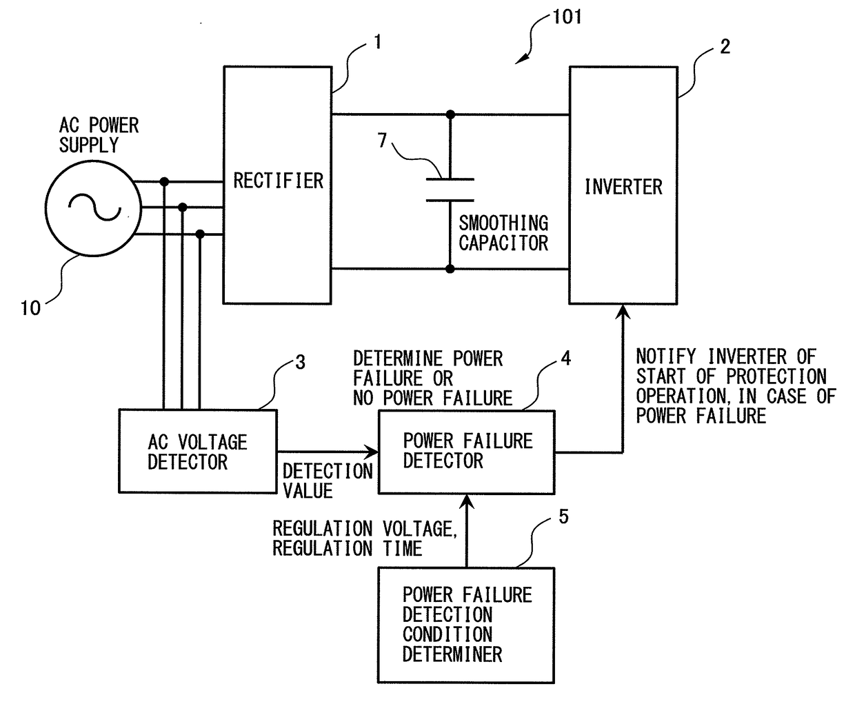
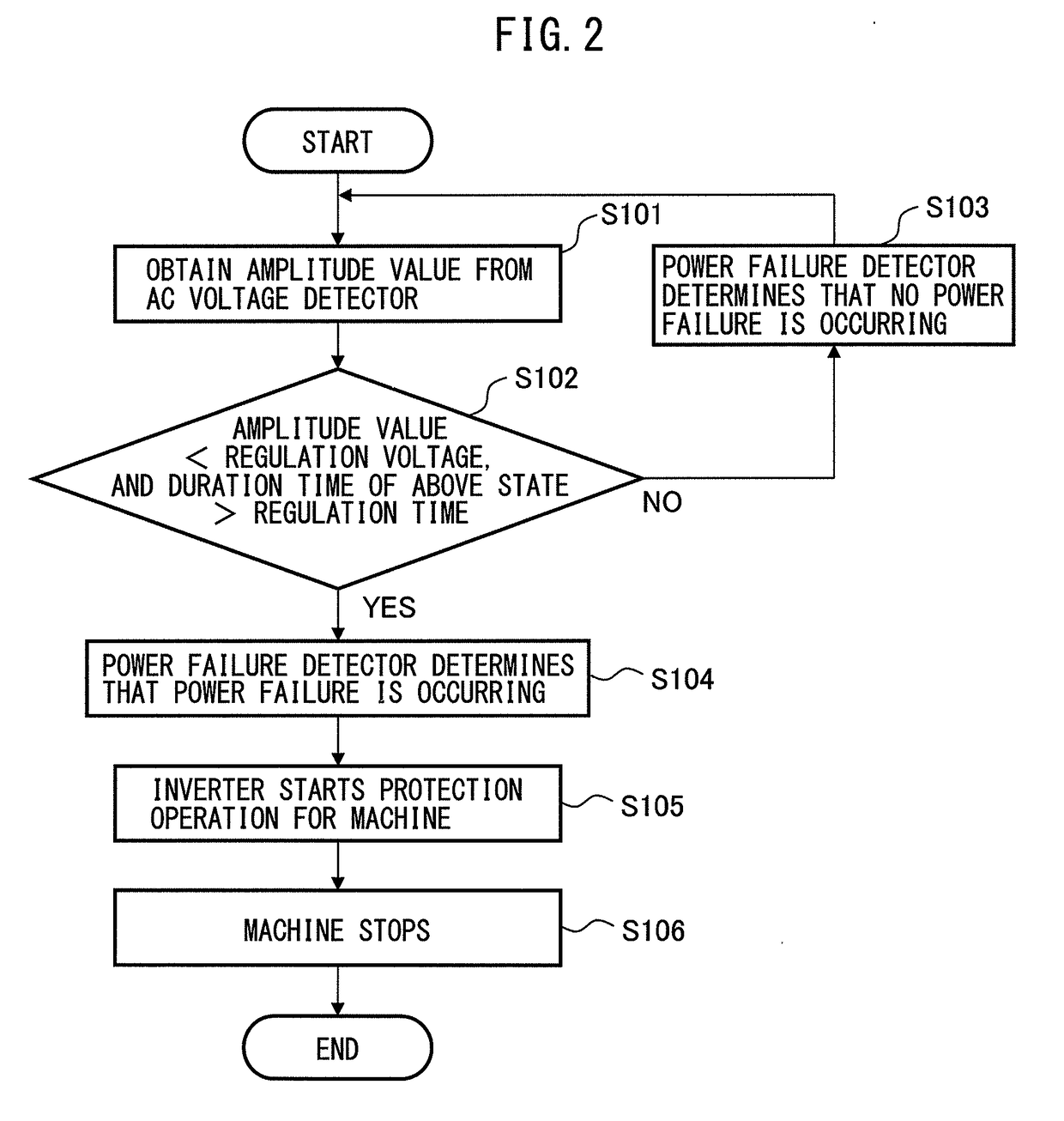
[0021]A motor controller according to a first embodiment of the present invention will be described. FIG. 1 is a block diagram of the motor controller according to the first embodiment of the present invention. A motor controller 101 according to the first embodiment of the present invention includes a rectifier 1, an AC voltage detector 3, a power failure detector 4, and a power failure detection condition determiner 5.

[0022]The rectifier 1 converts AC power supplied from an AC power supply 10 into DC power, and outputs the DC power. A smoothing capacitor 7 is provided in a DC link circuit on a DC output side of the rectifier 1.

[0023]The motor controller 101 according to the first embodiment of the present invention may further include an inverter 2. The DC power outputted from the rectifier 1 is smoothed by the smoothing capacitor 7, and then supplied to the inverter 2. The inverter 2 converts the DC power outputted from the rectifier 1 into desired AC power. The inverter 2 includ...

second embodiment

[0038]Next, a motor controller according to a second embodiment of the present invention will be described. FIG. 4 is a block diagram of the motor controller according to the second embodiment of the present invention. The difference between a motor controller 102 according to the second embodiment and the motor controller 101 according to the first embodiment is that the power failure detection condition determiner 5 modifies the regulation time in accordance with the power supply voltage of the AC power supply 10. The other configuration of the motor controller 102 according to the second embodiment is the same as that of the motor controller 101 according to the first embodiment, so a detailed description is omitted.

[0039]The power failure detection condition determiner 5 modifies the regulation time depending on the power supply voltage supplied from the AC power supply 10. The power failure detection condition determiner 5 preferably determines the detailed or changeable power ...


PUM


Abstract

A motor controller includes a rectifier for converting AC power supplied from an AC power supply into DC power and outputting the DC power; an AC voltage detector for detecting an AC voltage value of the AC power supply and outputting the AC voltage value as a detection value; a power failure detector for determining that a power failure is occurring, when a state in which the outputted detection value is equal to or lower than a regulation voltage has continued for a regulation time or more; and a power failure detection condition determiner for determining or modifying the regulation time.

Description

[0001]This application is a new U.S. patent application that claims benefit of JP 2016-062678 filed on Mar. 25, 2016, the content of 2016-062678 is incorporated herein by reference.BACKGROUND OF THE INVENTION[0002]1. Field of the Invention[0003]The present invention relates to a motor controller, and more specifically relates to a motor controller having the function of determining or modifying a condition for detecting a power failure of a power supply.[0004]2. Description of Related Art[0005]In cases of power failure that prevents the continuation of the normal operations of motor controllers and peripheral devices thereof, machines using the motor controllers are failed. Thus, the motor controllers generally include power failure detection means and perform protection operations to stop the machines before the continuation of the normal operations is hindered.[0006]The amount of energy that is required for continuing the normal operations of the motor controller and the periphera...

Claims


Application Information

Patent Timeline
IPC IPC(8): H02P29/024H02P27/06
CPCH02P27/06H02P29/025H02H7/09H02H3/247H02H3/253H02H1/00
Inventor TANAKA, SHUNPEIYAMAMOTO, KENTA
Owner FANUC LTD
Why Eureka
Try Eureka