
Distance measuring device and method for calibrating the same

Active Publication Date: 2017-09-28
KK TOPCON
View PDF0 Cites 2 Cited by
  • Summary
  • Abstract
  • Description
  • Claims
  • Application Information

AI Technical Summary

Benefits of technology

The present invention provides a technique for measuring distances with high precision without increasing cost. This is achieved by using pulsed signals that pass through band pass filters to convert detection signals into lower frequencies. This allows for the use of an A / D converter that operates at a relatively low sampling frequency. Additionally, the reference and measuring signals are input to the A / D converter at the same time, which reduces processing time and calculation errors. Furthermore, calibration processing decreases the margin of error that occurs due to variations in the phases, which are caused by the circuits.

Problems solved by technology

However, the overall time for the measurement is increased, and the amount of electrical power consumption is increased.
Technically, the phase of a signal varies when the signal passes through a circuit, and this phase variation caused by the circuit also affects the distance measurement precision.

Method used


Image

  • Distance measuring device and method for calibrating the same
  • Distance measuring device and method for calibrating the same
  • Distance measuring device and method for calibrating the same

Examples


first embodiment

1. First Embodiment

Structure

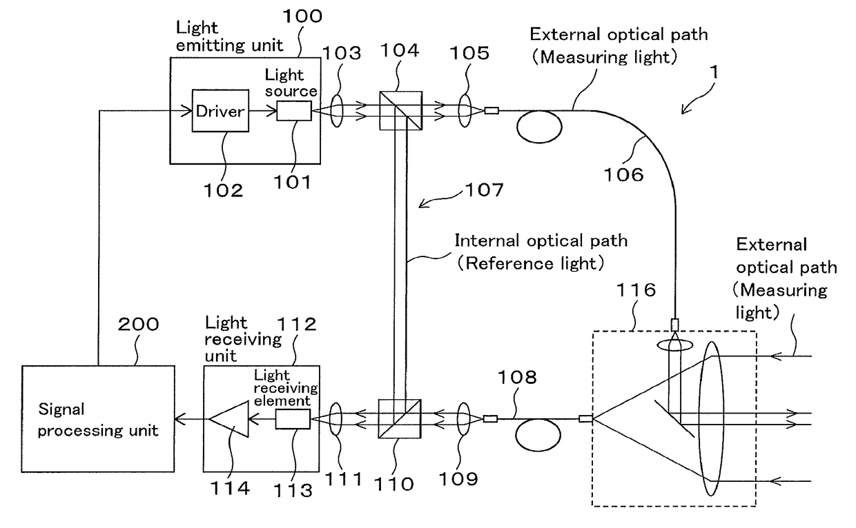
[0026]FIG. 1 shows a distance measuring device 1 that measures distances by using a phase difference measurement method. The distance measuring device 1 is configured to be mountable on a table of a tripod or the like. FIG. 1 shows a block diagram of the distance measuring device 1. Although not shown in FIG. 1, the distance measuring device 1 includes a power source, an interface for communicating with an external device, interfaces by which an operator can perform various operations, such as a control panel, a display, and the other units, and hardware and software that are the same as those equipped in a publicly known distance measuring device.

[0027]The distance measuring device 1 includes a light emitting unit 100. The light emitting unit 100 has a light source 101, which emits pulsed light to be used as measuring light and reference light, and has a driver 102 for driving the light source 101. Here, the measuring light is light that is emitted to an...

second embodiment

2. Second Embodiment

[0089]According to the First Embodiment, the added signal is processed by FFT analysis and is separated into the reference detection signal and the measurement detection signal, and then the phase difference between the reference detection signal and the measurement detection signal is detected and is used for calculating the distance to the object. This method is one of methods for calculating distances to objects based on added signals. The added signal contains information relating to the phase difference between the reference detection signal and the measurement detection signal.

[0090]For example, a first added signal may be obtained by adding a first reference detection signal and a first measurement detection signal together, and a second added signal may be obtained by adding a second reference detection signal and a second measurement detection signal together. At this time, if the phase difference between the first reference detection signal and the firs...


PUM


Abstract

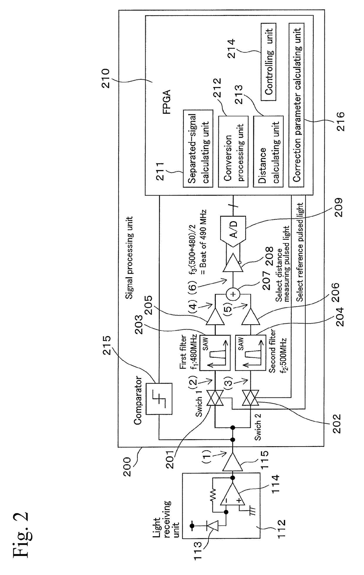
A distance calculating unit includes a first filter for a detection signal of reference pulsed light, a second filter for measuring pulsed light, an adder circuit that adds outputs from the two filters together, an A / D converter that receives output from the adder circuit, a separated-signal calculating unit that analyzes output from the A / D converter and that generates a first separated signal and a second separated signal, a conversion processing unit that converts the phase of at least one of the two separated signals into a phase of a predetermined frequency, and a distance calculating unit that calculates a distance to an object by using a phase difference between the two separated signals and a correction parameter, which is obtained by making the reference pulsed light pass through the first filter and the second filter at the same time and by calculating a phase difference between outputs from these filters.

Description

BACKGROUND OF THE INVENTION[0001]Technical Field[0002]The present invention relates to technology for measuring distances using pulses of light.[0003]Background Art[0004]Techniques for measuring distances by using pulsed light are publicly known. One such technique is disclosed in Japanese Unexamined Patent Application Laid-Open No. 2013-011558. These techniques can be performed with higher distance measurement precision by using pulsed light with a short pulse width. In accordance with these techniques, a phase difference between distance measuring pulsed light that has been reflected from an object, of which distance is to be measured, and reference pulsed light that has propagated through an internal optical path of a device, is detected and is used for calculating the distance.[0005]To process pulsed light that is detected, output of a light receiving element must be converted into a digital signal by an A / D converter. As the pulse width of the pulsed light is decreased, a sampl...

Claims


Application Information

Patent Timeline
IPC IPC(8): G01S7/497G01S7/486G01S17/08G01S7/4861G01S7/4865G01S17/10
CPCG01S7/497G01S7/486G01S17/08G01S17/10G01S7/4861G01S7/4865
Inventor TOKUDA, YOSHIKATSU
Owner KK TOPCON
Learn More